Wiring - model e1617, Wiring model e1617 – Liquid Controls XL LED Display E1615_E1616_E1617_E1618 User Manual
Page 10
wiring model E1617
Model E1617 of the LectroCount XL LED Remote Display is designed to receive a calibrated (50 pulses per
revolution) solid state quadrature pulse output. Typically, Model E1617 operates in conjunction with a solid state
quadrature pulser (PN 077733) mounted onto a mechanical register using mounting kit (PN 47824).
Since quadrature pulsers do not have an output signal to reset the LED Remote Display, a Reset Switch Kit (PN
82592) is required for this application. The Reset Switch Kit resets the XL LED Remote Display to zero between
deliveries. To complete the installation, the installer must provide a 12 VDC external power source and a junction box.
to wire the LectroCount XL LED Remote Display model E1617 to
a quadrature pulser:
1. Install Reset Switch Kit. page 16
2. Set the junction box.
3. Route the display’s shielded cable, the pulser wires, and the wires from the
external power source into the junction box. Use the appropriate connectors.
4. Connect the display’s shielded cable wires to the following pulser and
external power source wires:
• XL LED terminal 53 (red wire) to Pulser power (red wire) to External Power Source voltage (+Vo)
• XL LED terminal 54 (white wire) to Pulser signal (black/orange wire)
• XL LED terminal 55 (green wire) to Pulser signal (black/orange wire)
• XL LED terminal 56 (black wire) to Pulser ground (white wire) to External Power Source ground
5. Tighten connectors and close the boxes.
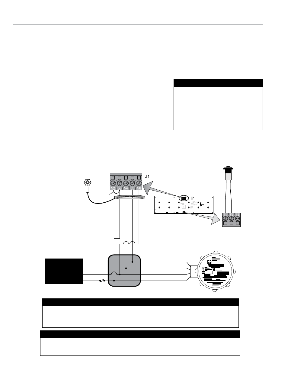
wIRInG - moDEL E1617
2A Fuse
Solid State Pulser
(50 Pulse Quadrature)
Junction Box
12 VDC
DC GND
Remote Display
PCB Board
GND
GND
Black/Orange
PWR/Red
GND (56)
A/
Green
(55)
B/
White
(54)
PWR/
Re
d (53)
VDC
Jumper
Black/Orange
EXTERNAL
POWER
SOURCE
Reset Switch
RES
COM
11
12
13
J2
Shieled cable
ground wire
grounded to
remote display
PCB board
A jumper is required between terminal 52 and terminal 53 on the display’s J1 terminal block. Display
units from the factory will include the jumper. When rewiring, ensure that this jumper is in place.
J1 Jumper - LectroCount XL LED Remote Display
The LectroCount XL LED Remote Display
is supplied with a 30 foot 4-wire shielded
cable with 22 gauge wire. If alternate
cabling is required, Liquid Controls
recommends a similar 4-wire shielded
cable with 22 gauge wire or larger and a
maximum cable length of 30 feet.
Shielded Cable
Quadrature pulse outputs can send a signal to the display to count either up or down. If the display
is counting in the wrong direction, switch the connections of signal wires from the pulser (black and
orange for PN 077733) to the display (J1 terminals 54 and 55) to reverse the counter direction.
Reversing the Display Counter Direction
10