Rate of flow switch kit - wiring – Liquid Controls XL LED Display E1615_E1616_E1617_E1618 User Manual
Page 15
wiring the Rate of Flow Switch kit (Pn 82593) -
moDEL E1615
The Rate of Flow Switch Kit is an optional accessory that toggles the LectroCount XL LED Remote Display from the
delivery volume to the current flow rate. To toggle to the current flow rate display, push select switch kit’s push button.
After 5 seconds, the display will return to the delivery volume. The select switch kit includes:
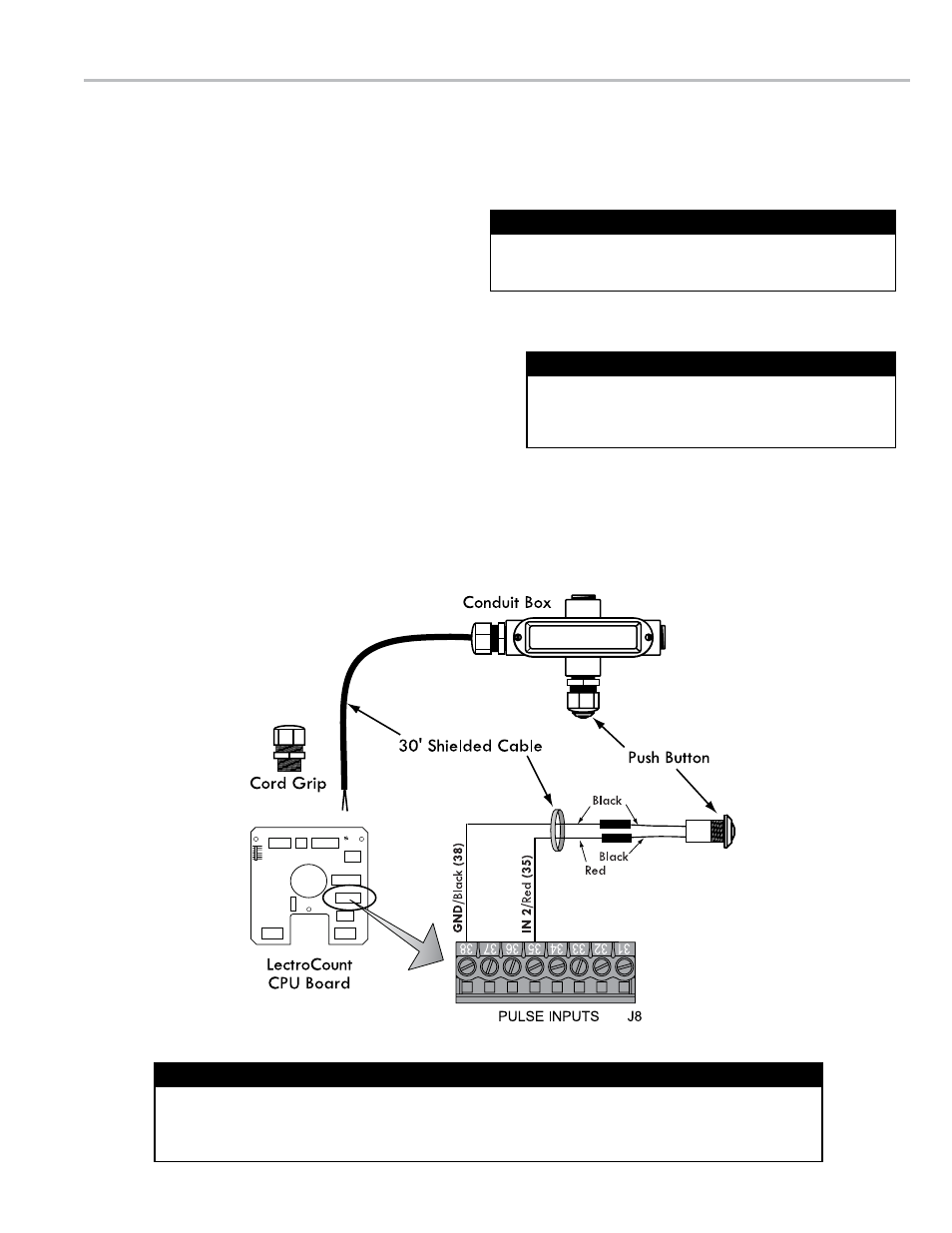
• Push button (w/ cord grip)
• Cord grip (2)
• 4-port conduit box
• 30', 2-wire, shielded cable
The switch kit accessory connects directly to a LectroCount LCR-II or LCR 600.
to install the Rate of Flow Switch kit:
1. Determine the best location for the push button.
2. Mount the conduit box at the determined location.
3. Screw a cord grip into the conduit box and a port in the
LectroCount register.
4. Route the 30' shielded cable through the cord grips in the conduit box and the LectroCount register and tighten the cord grips.
5. Screw the push button into the conduit box and connect the push button wires to the cable wires.
6. Connect the 30' shielded cable’s red wire to terminal 35 and black wire to terminal 38 on the J8 terminal block on the
LectroCount CPU board.
rate of floW sWItch kIt - WIrInG
The Rate of Flow Switch Kit is compatible with LectroCount
LCR-II and LCR 600 electronic registers only.
For Model E1615 Only
LectroCount XL LED Remote Displays are assembled and shipped ready for final cable termination.
If the display’s pre-installed shielded cable is removed during installation, be sure to secure the cable
and tighten the cover so the vapor seal is maintained. See page 18 for proper torque specifications.
Secure Cable and Tighten Cover Upon Reassembly
To function with an LCR 600, the Rate of Flow Switch
Kit must be wired to a 840404 CPU board flashed with
version 2.12 or higher of the SR600 firmware.
LCR 600 Software Requirements
15