Overview, Meter system components – Liquid Controls LCR 600 Install User Manual
Page 8
8
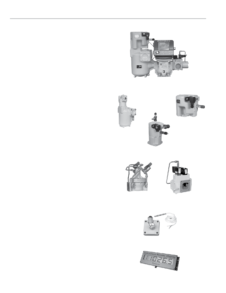
M7 Meter with LectroCount LCR 600 Electronic Register,
Optical Air Eliminator, High Capacity Strainer, and E-7 Valve
Optical Air Eliminator:
Refined Fuels
Mechanical Air
Eliminator and High
Capacity Strainer
Optical Vapor Eliminator:
LPG and NH
3
Solenoid Block
Valve
ETVC Kit
E-7 Valve
Remote Display
Meter system Components
MeTer sysTeM
A Liquid Controls meter system not only accurately
measures product, it also regulates and purifies product
flow in order to produce the optimal conditions for
measurement. Optimal systems typically include an air/
vapor eliminator, strainer, meter, register, and control
valve. The LectroCount LCR 600, a register, serves
as the central controller of the meter system. Most
components in the meter system are hard wired to the
LCR 600 via data communication cables. See manual
M100-10.
aIr/vaPor elIMInaTors
Air and vapor eliminators sense and remove air or
vapor in the piping before it enters the metering system,
ensuring that only liquid will pass through the meter for
measurement. Mechanical air eliminators do not require
a data connection to the LectroCount LCR 600 (in LPG
applications, they are often plumbed to a 3-way solenoid
which is wired to the LectroCount LCR 600). Optical air
eliminators use an optical sensor to monitor liquid levels
and a solenoid-actuated valve to turn the vapor vent on
and off. The optical sensor and the solenoid valve are
connected to the LectroCount LCR 600 by separate data
cables. See manuals M300-20 and M300-21.
valves
Valves control the flow through a metering system. They
open the line to initiate custody transfers and close the
line to stop custody transfers. Some valves can partially
close, slowing the flow rate to a dwell flow on preset
deliveries. By slowing the flow rate, valves can lessen
the hydraulic shock incurred by the meter system upon
shut off and provide accurate preset deliveries. Many
valves use solenoid-operated valves that require a hard
wired data connection to the LectroCount LCR 600. See
manuals M400-40 and M400-11.
eleCTronIC TeMPeraTure voluMe
CoMPensaTIon (eTvC) KIT
In order to perform temperature compensation
equations, the LectroCount LCR 600 relies on a
temperature probe inserted into the strainer housing.
Installation directions for the ETVC kit are included in
this manual.
leCTroCounT reMoTe dIsPlay
The 2¼" digits on the Liquid Controls LectroCount
Remote Display allow operators to view the register
totalizer values from distances of up to 100 feet. Hard
wire data communication with the LectroCount LCR 600
is required. See manual EM100-13.
overvIeW