Differential pressure (∆p) transducer, Differential pressure (∆p) transducer installation, Be careful with the cpu board – Liquid Controls LCR 600 Install User Manual
Page 25
25
DifferentiAl Pressure (∆P) trAnsDuCer
11
12
13
PRINTER
SERIAL 485
TERMINAL
POWER
COUNTER
MH1
CTS RXD TXD RTS
GND
GND
485+A
485-B
CTS RXD TXD RTS +VP
EART
H
GN
D
GN
D
IN
1
IN
2
IN
3
IN
4
+5V OU
T
+V
P
GN
D
+12-24
V
MH4
J20
J6
J3
J2
J1
J7
J7
C2
24
25
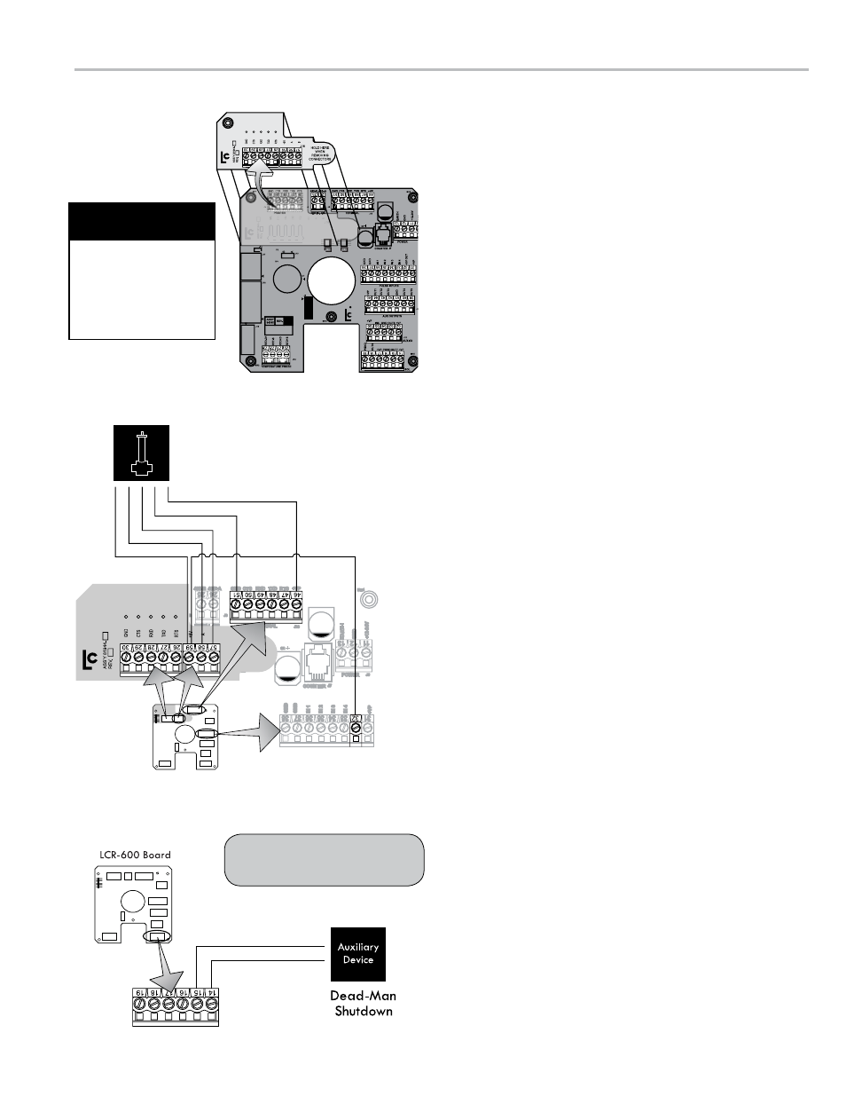
∆P Transducer
+5V(Out)/Jumper (59 to 32)
A/Blue (58)
+5V/Red (59)
B/Yellow (57)
GND/White (51)
+VP/Black (46)
B
The shutdown device should
draw no more than 1A.
When removing the J1
or J16 terminal from
the 81944 board, hold
down the right end of
the main CPU board to
prevent flexing.
Be Careful with the
CPU Board
Differential Pressure (∆P)
Transducer Installation
When ordered as part of a meter system with a LCR
600, Liquid Control’s ∆P transducer is wired to the
LCR 600 at the factory. The ∆P transducer can also be
ordered separately and installed onto a meter system
already in service. Refer to the ∆P transducer manual for
complete installation instructions. Instructions for wiring
the ∆P transducer to the LCR 600 are provided on this
page. The ∆P Transducer requires an additional board
(PN 81944) that mounts directly to the LCR 600 CPU
board. Typically, a ∆P transducer operates in conjunction
with a shutdown device, such as a valve or a dead-man.
The shutdown control must also be wired to the LCR 600
and should draw no more than 1 A.
to wire ∆P transducer to the lCr 600:
1. Unplug the J1, J2, and J3 terminal blocks from the LCR
600 CPU board. Leave the wires in the terminals.
2. Remove the screw at the top left corner of the LCR 600
CPU board.
3. Plug the 81944 board into the J1 connectors on the LCR
600 CPU board.
4. Fasten the top left side of both boards to the housing with
the screw provided wtih the 81944 board.
5. Plug terminal block J1 into the 81944 board. Plug J2 and
J3 back into the LCR 600 CPU board
6. Plug terminal J16 into the 81944 board.
7. Route the ∆P transducer cable through a cable gland in a
port on the back of the LCR 600. Secure the cable gland.
LC recommends running the cable through a cut to length
piece of weatherproof conduit.
8. Connect the four ∆P transducer wires to terminal block J3
on the LCR 600 CPU board and J16 on the 81944 board.
• Black to J3 terminal 46
• White to J3 terminal 51
• Yellow to J16 terminal 57
• Blue to J16 terminal 58
• Red to J16 terminal 59
9. Run the red jumper wire (provided with the ∆P transducer
kit) from the J8 terminal 32 to J16 terminal 59 (+5V).
10. Route two wires (AWG determined by device) cable from
the shutdown control device through a cable gland in a
port on the back of the LCR 600. Secure the cable gland.
LC recommends running the cable through weatherproof
conduit.
11. Connect the two wires from the shutdown control device
to terminal block J13,
• J13 terminal 14 is the +12VDC output
• J13 terminal 15 is the switching output