Laurel Electronics Ethernet Node Configuration for Series 2 Digital Panel Meters, Counters, Timers, Transmitters and Ethernet-to-Serial Device Servers User Manual
Page 8
8
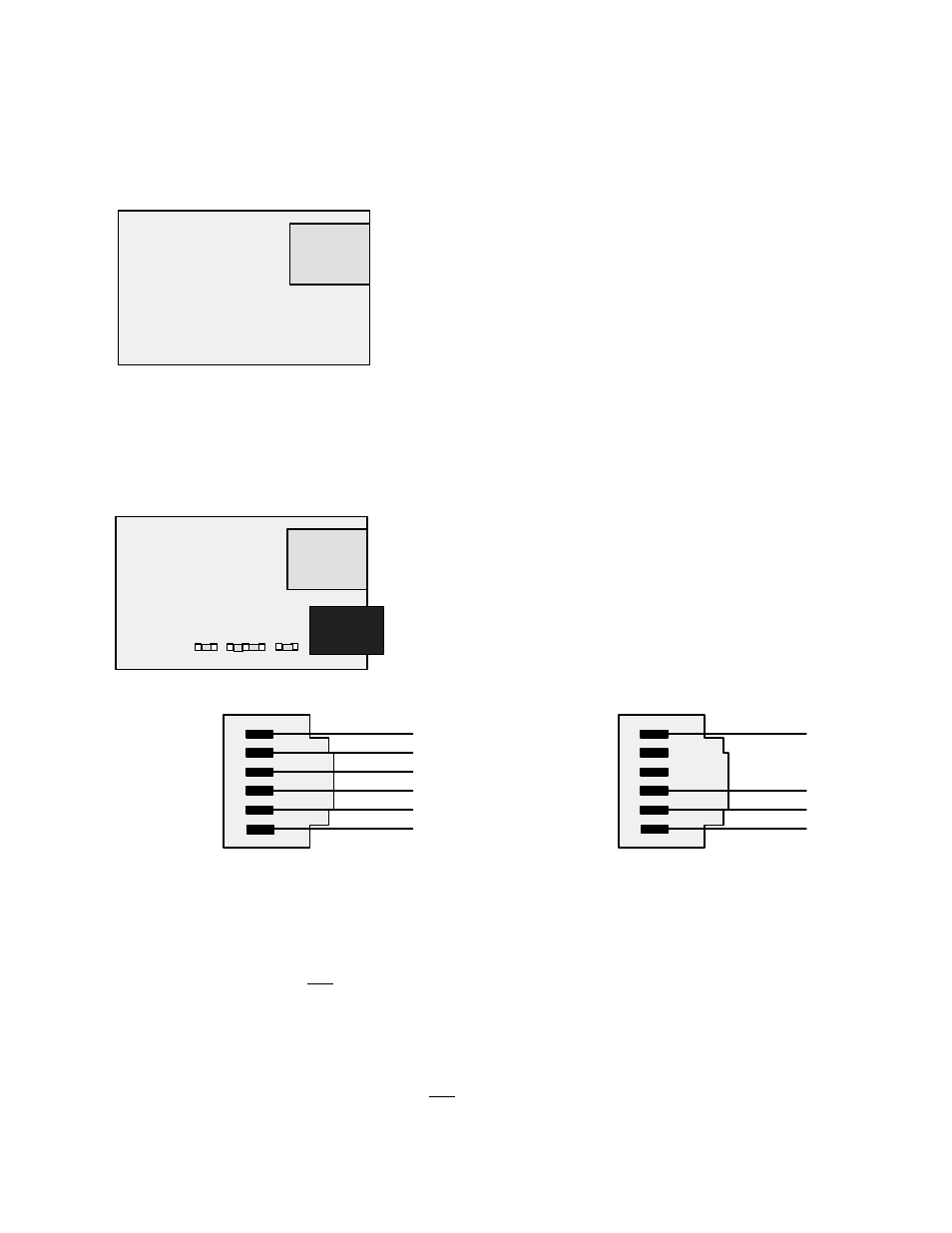
3. Connection of 1/8 DIN meters
Basic Ethernet panel meters use an LNET Ethernet option board with an RJ45 jack for direct
connection to a computer, router, switch or hub via an Ethernet cable.
RJ45
Ethernet
Interface
Board
Basic Ethernet meter board
No jumpers needed.
Ethernet-to-serial device server meters with an LNET485 option board can function as normal
meters for measurement and control purposes and also as a device server. This option board
features and RJ485 jack to the Ethernet plus an RJ11 jack which can support up to 31 remote
meters via an RS485 bus in daisy chain fashion.
RJ45
Ethernet-to-
RS485 Server
Board
b
d
RJ11
a
c
Ethernet-to-serial device server meter board
Full duplex: No jumpers for short cable runs.
Add a + c for long cable runs.
Half duplex: b + d. Add a for long cable runs.
6
5
4
3
2
1
ISO GND
BRX (RX+)
ARX (RX-)
ATX (TX-)
BTX (TX+)
ISO GND
6
5
4
3
2
1
ISO GND
TX- / RX-
TX+ / RX+
ISO GND
Full duplex operation
Half duplex operation
Wiring of RJ11 jack of Ethernet-to-serial device server board
The meters on an RS485 bus need to be equipped with our L485 RS485 digital interface board
with dual 6-pin RJ11 jacks, not our LMOD RS485 digital interface with dual 8-pin RJ45 jacks. The
dual 6-pin RJ11 jacks on the L485 RS485 board are wired in parallel to allow multiple meters to
be daisy-chained using readily-available 6-wire data cables with no need for hand-wiring or an
RS485 hub. The outer two wires are used for ground.
Use 6-wire, straight-through data cables, not 4-wire telephone cables or crossover cables, all the
way from the device server to the last device on the RS485 bus. Connect ATX to ATX, BTX to BTX,
etc., with no crossover as you go from device to device.