Laurel Electronics Ethernet Node Configuration for Series 2 Digital Panel Meters, Counters, Timers, Transmitters and Ethernet-to-Serial Device Servers User Manual
Page 7
7
2. Hardware Overview
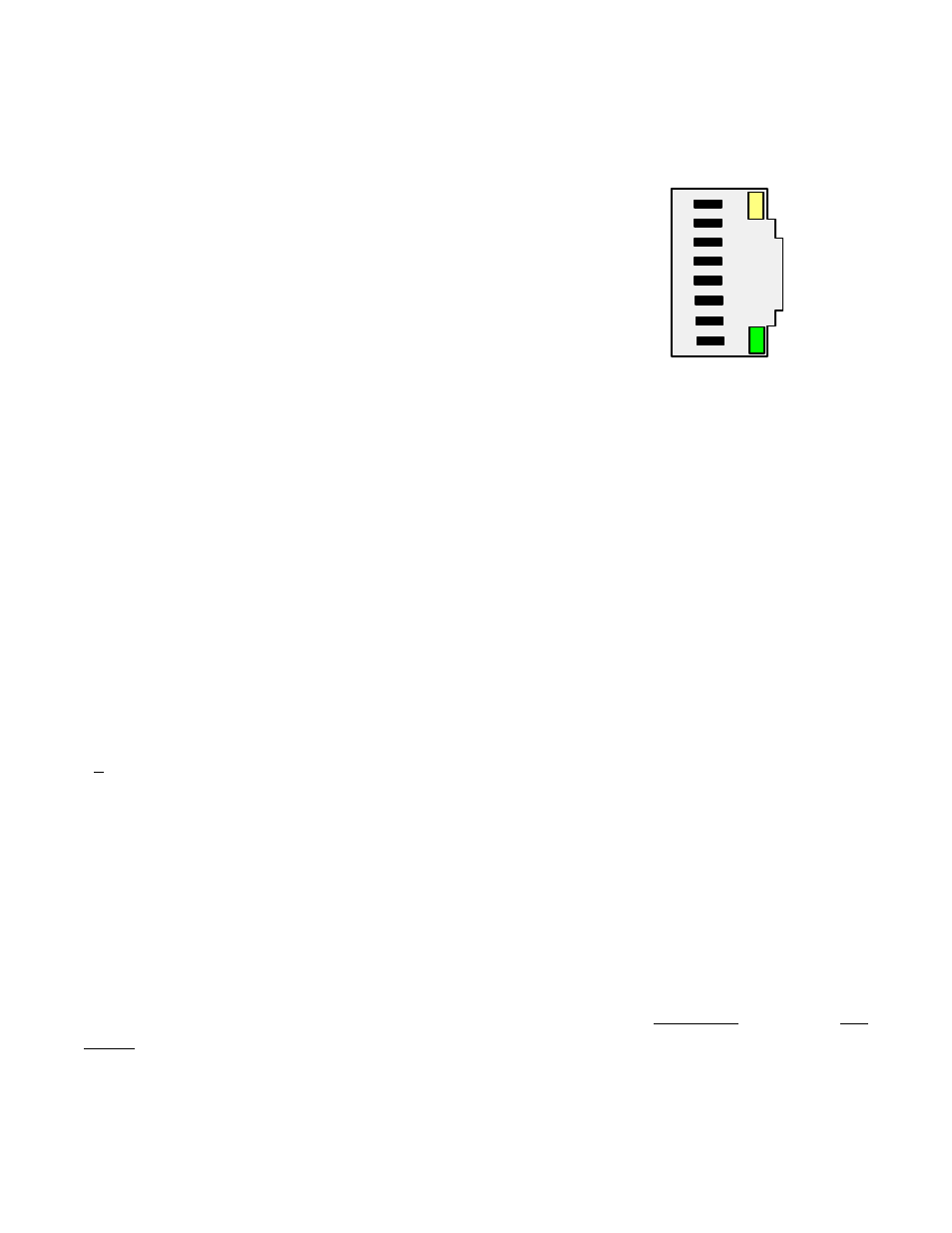
The Ethernet connector for all of our Nodes is provided by an RJ45 jack, Green and amber LEDs
on the jack indicate network operation:
1) Following power-up, the green and amber LEDs are on
steady until an IP address has been assigned to the Node.
2) Once an IP address has been assigned to the Node, the
amber LED is turned off. It will light up whenever the Node
detects data packet activity.
3) When the Node has made a TCP connection, the green LED
alternates on (1 sec) and off (1 sec), while the amber LED is
on steady.
Ethernet cables (CAT5 or better) can be straight-through or crossover. Our Nodes automatically
adapt for either.
An LNET option board is used in our Ethernet panel meters and counters. This board has an RJ45
jack for direct connection to a computer, router, switch or hub via an Ethernet cable.
An LNET485 option board is used in our Ethernet-to-serial device server meters. This board has
an RJ45 jack to the Ethernet plus an RJ11 jack which supports up to 31 remote meters on an
RS485 bus. The remote meters must be equipped with our L485 RS485 serial communication
board with dual RJ11 jacks. These allow the remote meters to be daisy-chained using readily-
available, straight-through, 6-wire data cables with no need for hand-wiring or an RS485 hub.
LTE Series Ethernet transmitters feature an RJ45 jack for the Ethernet in lieu of the 6 screw
terminals that would otherwise be standard for RS232 and RS485 with our transmitters.
LTNET485 DIN-rail Ethernet-to-serial device servers feature an RJ45 jack to the Ethernet, an
RJ11 jack for connection to remote meters via an RS485 bus using 6-wire data cables, plus 5
screw terminals for connection to LT Series transmitters via discrete wires to an RS485 bus. All
our LT Series transmitters come standard with a screw terminal RS485 interface.
Half or full duplex RS485 communications (2 data wires + ground or 4 data wires + ground) can
be selected via jumpers on our LNET485 or LTNET485 Ethernet-to-serial device servers and on the
devices on the RS485 bus. If the RS485 bus is implemented with screw terminals, half-duplex
selection can also be made by shorting ATX to ARX and BTX to BRX at the screw terminals.
Shorting these wires at the connector is electrically equivalent to using jumpers on the board.
RS485 Termination Resistors should be inserted via jumpers on the server end and on the last
device on an RS485 line longer than 200 feet (60 m). Do not install more than these two sets of
jumpers on an RS485 line, as this could add an excessive resistive load and draw down the
voltage on the line. First try operating without termination resistors.
Ethernet Indicators
8
7
6
5
4
3
2
1
Amber LED
Green LED
RX -
RX +
TX -
TX +