Laurel Electronics Ethernet Node Configuration for Series 2 Digital Panel Meters, Counters, Timers, Transmitters and Ethernet-to-Serial Device Servers User Manual
Page 11
11
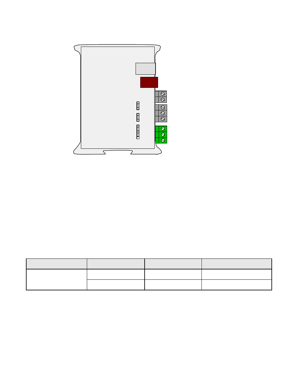
4.2 LTNET485 Ethernet-to-RS485 Device Server
3 Power GND
2 AC neutral or -DC
1 AC high or +DC
5 ARX (RX-)
4 ATX (TX-)
3 GND
2 BRX (RX+)
1 BTX (TX+)
RJ11
RJ45
P4 Ethernet
P3 RS485
a
b
c
d
E6
P2
P1
The LTNET485 Ethernet-to-serial device server features an RJ45 Ethernet connector for direct
connection to a computer, router, switch or hub via an Ethernet cable, plus an RJ11 RS485
connector which is wired in parallel to five screw terminals. These additional connections allow
the server to support a total of 31 meters and transmitters on an RS485 bus.
The RJ11 connector is designed for use with our meters having the dual 6-pin RJ11 RS485 com-
munication option. These jacks allow multiple meters to be daisy-chained using readily-available
6-wire straight-through data cables with no need for hand-wiring or an RS485 hub.
The five screw terminals are designed for use with our non-Ethernet transmitters, which provide
screw terminals for RS485 I/O as a standard feature. Using screw terminals on the server and
transmitter ends allows data transmission via five discrete wires, with no need for adapters.
Serial Signal
Duplex
Jumpers
Termination Resistor*
Full
None
E6 a + c
RS485
Half
E6 b + d **
E6 c
* Only install termination resistor(s) if the device server is at one end of an RS485 line longer
than 200 feet (60 m).
** Or externally jumper BTX to BRX and ATX to ARX (same effect as internal jumpers).