Laurel Electronics Ethernet Node Configuration for Series 2 Digital Panel Meters, Counters, Timers, Transmitters and Ethernet-to-Serial Device Servers User Manual
Page 12
12
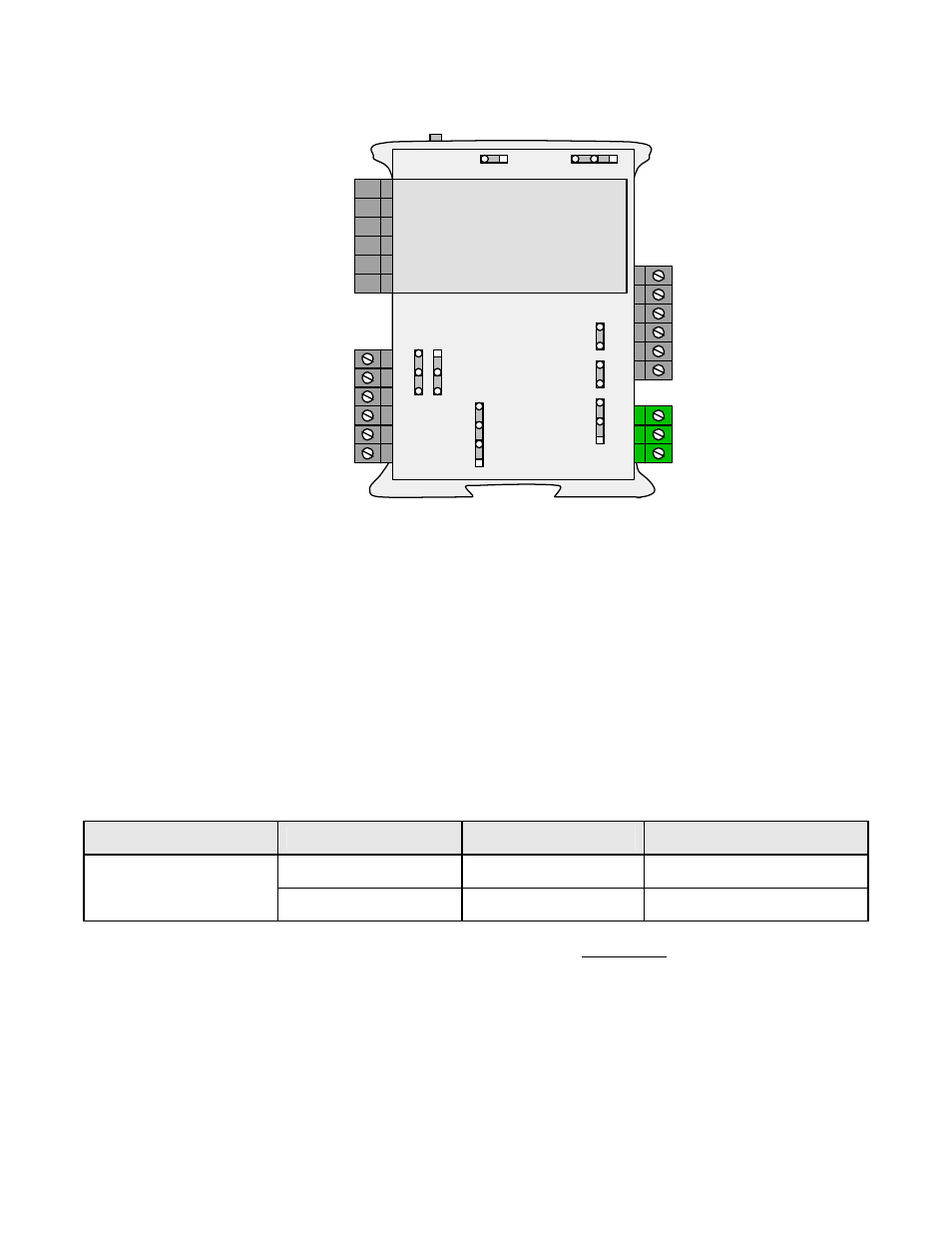
4.3 LT Series DIN-Rail Transmitters on an RS485 Bus
P4 Analog
output (standard)
P3 Solid state
relays (normally
open, standard)
P5 Signal
input &
excitation
output
Ana out - 1
Ana out +
2
Alarm 2 1
Alarm 2 2
Aalrm 1 3
Alarm 1 4
Signal
conditioner
board
RS485
6 N/C
5 ARX
4 ATX
3 GND
2 BRX
1 BTX
3 Power GND
2 AC neut or -DC
1 AC high or +DC
RS232
TX
RX
NC
GND
GND
NC
P1 Power input
E1
E4
a
b
a
b
c
d
E2
b
a
d
c
a
b
c
E3
E6
P2 Communications
Reset
LT Series transmitters on an RS485 bus offer RS485 data I/O as a standard feature along with an
isolated 4-20 mA, 0-20 mA or 0-10V analog output and dual 120 mA solid state relays for alarm or
control. Signal conditioner boards are available for all popular industrial analog, frequency and
pulse-type transducer signals.
For Ethernet connectivity, connect up to 31 LT Series transmitters to our LTNET485 DIN-rail
Ethernet-to-serial device server using discrete, parallel wires in daisy chain fashion from the
server to each transmitter.
• For full-duplex communications, use five wires to connect BTX to BTX, BRX to BRX, ATX to
ATX, ARX to ARX, and GND to GND, all in daisy chain fashion without crossover.
• For half-duplex communications, use three wires to connect A to A, B to B, and GND to GND.
Serial Signal
Duplex
Jumpers
Termination Resistor*
Full
None
E6 a + c
RS485
Half
E6 b + d **
E6 c
* Only install termination resistor(s) if the transmitter is the last device on an RS485 line longer
than 200 feet (60 m).
** Or externally jumper BTX to BRX and ATX to ARX (same effect as internal jumpers).
To reset the transmitter (same as power-up), press the Reset button.
To reset communications to 9600 baud, command mode, Custom ASCII protocol, and Address 1,
place a jumper at E1 and power up the transmitter, then remove the E1 jumper.
Other jumper positions are as for our LTE Ethernet Transmitter Node (Section 4.1).