Laurel Electronics Ethernet Node Configuration for Series 2 Digital Panel Meters, Counters, Timers, Transmitters and Ethernet-to-Serial Device Servers User Manual
Page 14
14
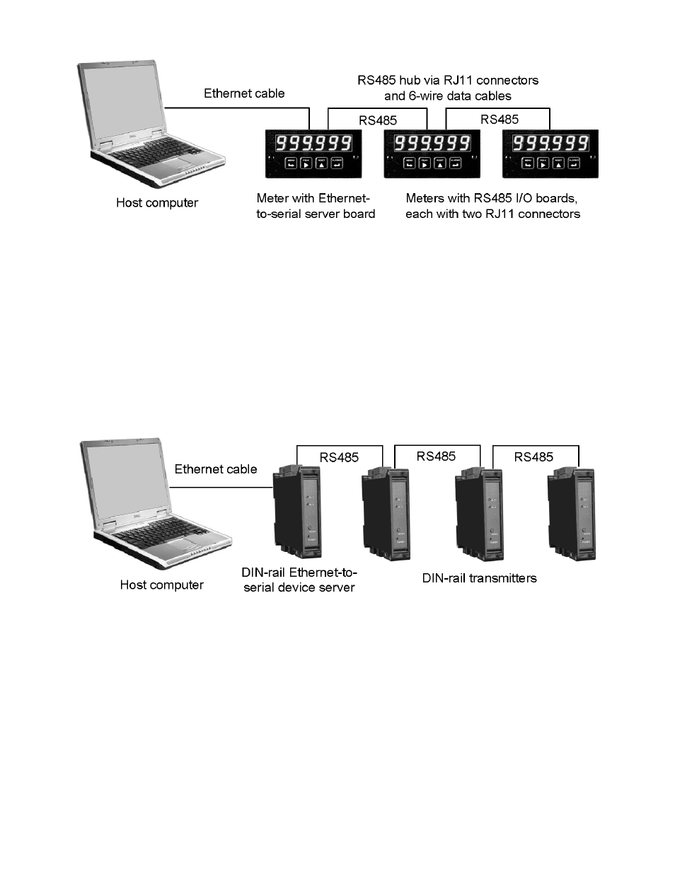
Example 3. The host computer is connected to a first meter with an LNET485 Ethernet-to-
serial server board via an Ethernet cable. This first meter can take measurements and also
serves as the host for an Ethernet-to-serial server board. That board is acts as the Ethernet
gateway for the host meter and for up to 31 other meters via commercial 6-wire RS485 data
cables in daisy-chain fashion. Upon power-up, the Node will wait about 25 seconds to decide
that no dedicated DHCP server is present, then sets itself up as a DHCP server. It will assign
a local IP address to itself and to the computer, creating a LAN consisting of the Ethernet
board and host computer. The Ethernet board also serves as an RS485 server to address all
meters on the RS485 line.
Example 4. The host computer is connected to an LTNET485 DIN-rail Ethernet-to-serial
device server in a DIN rail mount package. This device server provides an RS485 interface
for up to 31 RS485 devices, which can be a mix of transmitters and meters. Connection to
transmitters can be via 5 discrete parallel wires for full-duplex RS485, or via 3 discrete
parallel wires for half-duplex RS485. Connection to meters (not illustrated) is via 6-wire data
cables and RJ11 jacks. After waiting 25 seconds, the device server automatically sets itself
up as a DHCP server and as an Ethernet Node, assigning a local IP address to itself and to
the computer.