Impulse 463E User Manual
Page 65
© Sealevel Systems, Inc.
- 62 -
SeaI/O User Manual
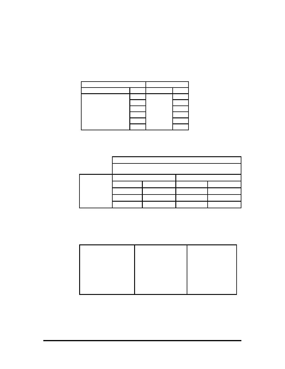
(0x64) Set A/D, D/A Configuration
SeaI/O devices featuring analog to digital or digital to analog conversions can be
configured via a Modbus command. Upon a successful operation, the SeaI/O module
will respond with the response packet shown below.
Request
Response
Field Name
(Hex)
Field Name
(Hex)
Function
64
Function
64
Device Config
00
Channels 1-4 Config
00
Channels 5-8 Config
00
Channels 9-12 Config
00
Channels 13-16 Config
00
The configuration byte stream is defined as follows:
BYTE
BIT
7
BIT
6
BIT
5
BIT
4
BIT
3
BIT
2
BIT
1
BIT
0
Device Config
A/D Voltage Reference
A/D Channel Mode
1-4 Config
Ch 1 Range
Ch 2 Range
Ch 3 Range
Ch 4 Range
5-8 Config
Ch 5 Range
Ch 6 Range
Ch 7 Range
Ch 8 Range
9-12 Config
Ch 9 Range
Ch 10 Range
Ch 11 Range
Ch 12 Range
13-16 Config
Ch 13 Range
Ch 14 Range
Ch 15 Range
Ch 16 Range
The actual values for the configuration options above (A/D Voltage Reference, A/D
Channel Mode, and A/D Ch xx Ranges) are enumerated in SeaMaxW32.h, included
with the SeaMAX libraries, and shown in the table below.
A/D Voltage Reference
A/D Channel Mode
Ch xx Ranges
ANALOG_OFFSET = 0
SINGLE_ENDED
= 0
ZERO_TO_FIVE = 0
GND_OFFSET
= 1
DIFFERENTIAL
= 1
PLS_MIN_FIVE
= 1
AD_REF_OFFSET
= 2
CURRENT_LOOP = 2
ZERO_TO_TEN
= 2
DA_CHANNEL_1
= 4
PLS_MIN_TEN
= 3
DA_CHANNEL_2 =
8