Impulse 463E User Manual
Page 43
© Sealevel Systems, Inc.
- 40 -
SeaI/O User Manual
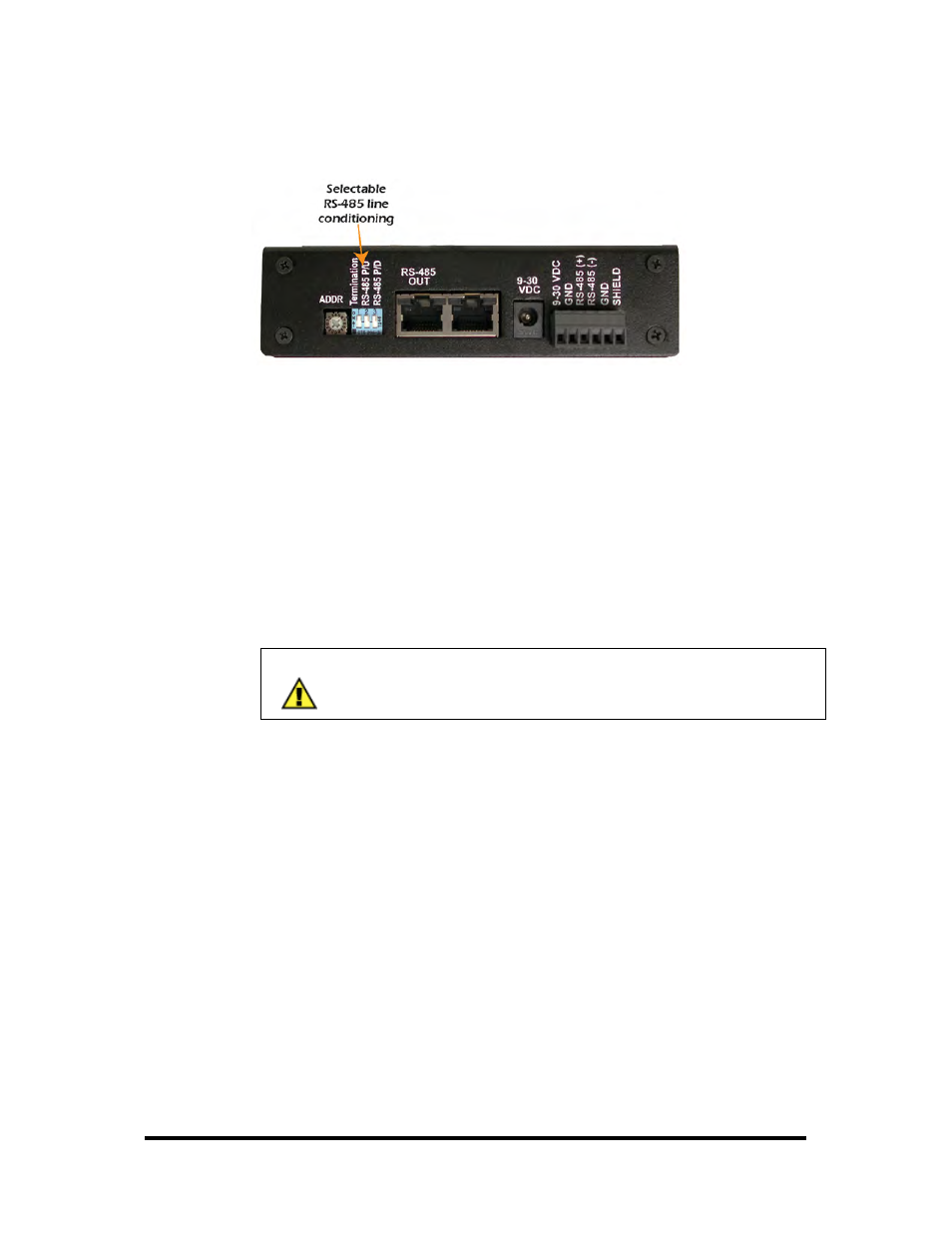
Setting Termination & Pull-Up/Pull-Down Resistors
A “stack” or “chain” of SeaI/O modules, connected via the pass-through connectors
or screw terminals on the left side of the enclosure, communicates via an RS-485 bus,
which must be properly terminated to work correctly. A set of three dipswitches is
located on the left side of enclosure, next to the “ADDR” rotary switch. These
switches control line termination and the RS-485 pull-up and pull-down resistors.
The pull-up and pull-down resistors ensure that the input ports are at a known state
when not being driven by the RS-485 line. In most cases, all three of the dipswitches
on each SeaI/O module should be in the down position, except the two end modules.
The first and last SeaI/O modules in the chain should have all three dipswitches in the
up (enabled) position.
NOTE:
Make sure that only the first and last SeaI/O modules have line
termination enabled (up position). Improper termination settings
can result in invalid data or communication failures.