Hardware configuration – Impulse 463E User Manual
Page 21
© Sealevel Systems, Inc.
- 18 -
SeaI/O User Manual
Hardware Configuration
The SeaI/O-463 and SeaI/O-470 are the only two modules that require you to open
the enclosure. On all SeaI/O modules, most device settings can be configured on the
left side of the SeaI/O module. Refer to the SeaI/O Hardware Description section
of this manual for a list of common features available and settings that can be
changed on the left side of the SeaI/O module.
When connecting more than one SeaI/O module to a host computer, you will need to
set the device address (Slave ID). This can be done in software or by using a rotary
switch on the left side of the enclosure. Refer to the SeaMAX Application Suite
section where you can find instructions for configuring the device address (Slave ID)
and setting the termination pull up and pull down resistors.
SeaI/O-463 Ribbon Cable Installation Instructions
A copy of these instructions are included with the SeaI/O-463 module and can also
be downloaded from the SeaI/O-463 product page on the Sealevel website.
NOTE:
Do not perform these instructions with the power connected. Be
sure to follow proper ESD procedures by grounding yourself and the
SeaI/O module.
What you will need:
SeaI/O-463 module
Phillips head screwdriver
Slotted screwdriver
50-pin IDC ribbon cable* (up to four)
*Ribbon cable accessories available:
•
CA167 – 40” IDC 50-pin to IDC 50-pin ribbon cable
•
CA197 – 18” IDC 50-pin to IDC 50-pin ribbon cable
•
CA135 – 40” IDC 50-pin to 50-pin edge connector ribbon cable
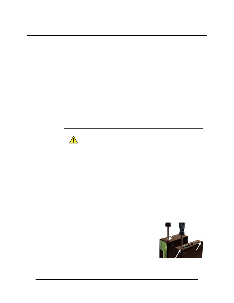
Step 1
Remove the terminal block from the left side and
then remove the two black screws from each side
of the module as shown in the image.