Wall), Surface, flush) – DoorKing 1833 PC Programmable User Manual
Page 48
1835-065-E-7-13
46
NC
NO
NO
RING
HF
1816
HS
NC
C
ON
CLK
SEN
SPK
VOL
FEED
BACK
RS 232
ELEVATOR
12
12
34
5
6
7
8
9
10
11
12
13
14
1
2
3
MIC
VOL
OFF
KEYPAD
3 2 1
3 2 1
3
2
1
MASTER
CODE
16AC
16AC
BAT
1NO
1NC
1C
2RY
2C
A
Z
IMC
5VDC
IMD
SPKR
COM
MIC
PSW
CGND
PHONE
1
8
35
sn XX
THIS SIDE UP
0000010100010
APB
3000
BACKLITE
CUTOFF
CONTRAST
8 LINE
DISPLAY
DOORKING 1892-010
3 2 1
SINGLE
LINE
DISPLAY
CONTRAST
DOORKING 1891-010
CONTRAST
DOORKING 1896-012
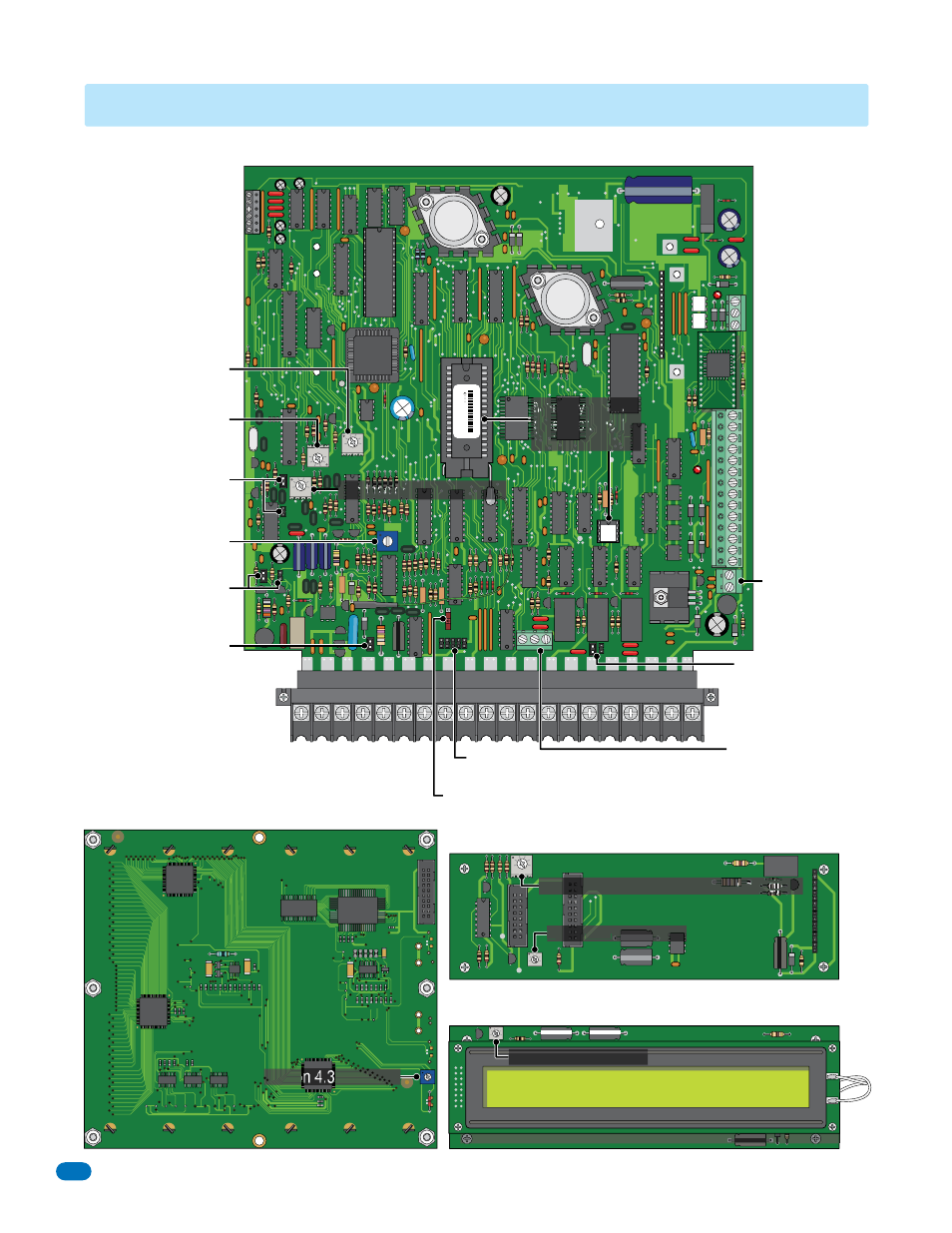
1830 Series Circuit Board
1837 LCD Display Board
1834,1835
(Wall),
1837 LCD Interface Board
1834, 1835 LCD Display Boards
(Surface, Flush)
SECTION 4 - ADJUSTMENTS
RS-232 Terminal
(see section 2.4.2)
Elevator Control
Terminal
1833
1835
1837
(see section 2.1-
Expansion boards
and elevator
control and 2.2)
Auxiliary Terminal
1833
1835
1837
(see section 2.2)
1834 Aux
Terminal Only
(see section 2.2)
Relay 2 Jumper:
Normally Open (NO)
Normally Closed (NC)
(see section 4.7)
Relay 0 Terminal:
Normally Open (NO)
Normally Closed (NC)
Common (C)
(see section 2.2)
Keypad
Connector
Master Code Switch
(see sections 3.2.1 and 4.5)
Ring Pin Jumper
(see sections
3.1 and 4.6)
Click Sensitivity
(see section 4.2)
Speaker Volume
(see section 4.1)
Microphone Volume
(see section 4.1)
1816 Interface Jumper
(see section 4.8)
Hands Free (HF) /
Hand Set (HS) Jumper
(see section 4.9)
Main Terminal (2.2)
Section 4.3 - Contrast
Contrast - Section 4.3
8 LINE
8 LI
DISPLAY
DI
E
LAY
Contrast - Section 4.3
Backlite Cutoff - Section 4.4 Do not adjust
Feedback (see section 4.1)
Memory Chips
(see sections 1.5
and 3.1.3)
RELA
Y-0
RELA
Y-2
RELA
Y-1