2 terminal descriptions, Main terminal, Nc no – DoorKing 1833 PC Programmable User Manual
Page 21
1835-065-E-7-13
19
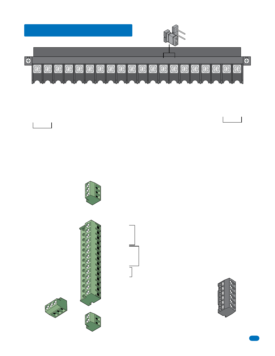
2.2 Terminal Descriptions
Phone Line Connection
16AC
16AC
BAT
1NO
1NC
1C
2RY
2C
A
Z
IMC
5VDC
IMD
SPKR
COM
MIC
PSW
CGND
PHONE
1
2
3
4
5
6
7
8
9
10
11
12
13
14
15
16
17
18
19
20
Main Terminal
16 V
AC Input Power
16 V
AC Input Power
Back-up Batter
y POSITIVE
For Phone System Only
. (connect negative to terminal 6)
Relay 1 Normally Open – 30 V
o
lt, 3 Amp max.
Relay 1 Normally Closed – 30 V
o
lt, 3 Amp max.
Relay 1 Common – 30 V
o
lt, 3 Amp max.
Relay 2 Contact – 30 V
o
lt, 3 Amp max.
Relay 2 Common – 30 V
o
lt, 3 Amp max.
“A” Button Input.
“Z” Button Input.
14 +12 VDC Power.
13 Common.
12 DATA 1.
11 DATA 0.
10 +12 VDC Power.
9 Common.
8 DATA 1.
7 DATA 0.
6 16 VAC Output.
5 16 VAC Output.
4 Back-up Battery NEGATIVE (For Weigand Only).
3 Back-up Battery POSITIVE (For Weigand Only).
2 16.5 VAC Input Power – 20 VA.
1 16.5 VAC Input Power – 20 VA.
(Powers RS-232, elevator control and Weigand)
2 16.5 VAC Input Power – 20 VA.
1 16.5 VAC Input Power – 20 VA.
(Powers RS-232)
1 DATA 1 – Connect to terminal 20 of elevator control board.
2 DATA 0 – Connect to terminal 21 of elevator control board.
3 COMMON – Connect to terminal 22 of elevator control board.
Transmit Data 1
Receive Data 2
Request to Send 3
Clear to Send 4
Signal Ground - Shell 5
Not used 6
(Not used).
5 VDC Power for LED lighting.
(Not used).
Speaker Output.
Common for switch input #4, microphone,
speaker
, AZ & CALL buttons and batter
y neg.
Microphone Input.
Switch Input. A closure between terminals 4 and 6 will cause the designated relay(s) to activate for
the programmed strike time or dial a phone number – see 3.2.7. The Postal Switch is connected here.
Earth Ground Only
(See Section 2.1.3)
.
Phone Line Connection
3
2
1
14
12
13
11
10
9
8
7
6
5
4
3
2
1
2
1
Aux Terminal
Removable
RS-232
Terminal
Removable
Elevator Control
Terminal
Non-Removable
1834 Aux Terminal ONLY
Non-Removable
Relay 0 Terminal
Non-Removable
Note: Connect to the Elevator Control Board (2348-010).
See Elevator Control Board Manual 2348-065 for more info.
100 ft. max. with 1
8
A
WG wire.
200 ft. max. with 16 A
WG wire.
20 V
A
min. for 1
8
33, 1
8
34 and 1
8
35, 40 V
A
min. for 1
8
37.
8
00 ft. max. with 24 A
WG wire.
1600 ft. max. with 22 A
WG wire.
(Wiring
MUST
be twisted and completely isolated from the ground)
See section 4 on page 46 for the locations of the terminals on the circuit board.
Note: The 14-pin aux terminal can be removed for easy
wiring. Expansion boards are connected here when used.
See Expansion
Board Manual
2351-065 and
section 2.3.2,
2.3.3 for more
information.
Note: Located in the upper left corner of circuit
board. The 6-pin terminal can be removed for
easy wiring. Connects a PC (See Section 2.4.2).
Relay 2 Note: Normally Open and
Normally Closed relay jumper is
used to set Relay 2 input on the
circuit board (See section 4.7).
NO
NC
C
Normally Open – 30 V
olt, 3 Amp max.
Normally Closed – 30 V
olt, 3 Amp max.
Common – 30 V
olt, 3 Amp max.
1
2
3
4
5
6
NC
NO
Weigand input (Card Reader)
activates Relay 1 for
programmed strike time
Weigand input (Card Reader)
activates Relay 2 for
programmed strike time
For card readers that have additional
lighting for outdoor use.
(NOT available for the 1834.)
(NOT available for the 1834.)
(NOT available for the 1834.)