3 manual gate operation, Unlock manual crank access panel, Caution – Controlled Products Systems Group 9210-081 User Manual
Page 37
9210-065-F-4-12
35
WA
RN
ING
MO
VIN
G G
ATE
CA
N C
AU
SE
Op
era
te g
ate
on
ly wh
en g
ate
are
a is
in s
igh
t
and
fre
e o
f p
eop
le a
nd o
bstr
ucti
ons
.
Do
no
t allo
w c
hild
ren
to p
lay
in
ga
te a
rea
or o
per
ate
ga
te.
Do
no
t sta
nd i
n g
ate
pa
th o
r wa
lk t
hro
ugh
path
wh
ile
ga
te i
s m
ovin
g.
Rea
d o
wn
er’s
m
anu
al a
nd s
afe
ty in
stru
ctio
ns.
SE
RIO
US
INJ
UR
Y O
R D
EAT
H
CLA
SS
CER
TIF
IED
TO
CA
N/
CS
A C
22
.2 NO.
247
CONFOR
MS
TO
ANS
I/U
L-
325
VEHI
CU
LA
R G
AT
E OP
ERA
TOR
HP
53
382
MODE
L
SERI
AL
VOL
TS
PH
AS
E
AM
PS
60
Hz
MA
X GA
TE
LOA
D
Doo
rKin
g,
Inc
.,
Ing
lewo
od,
CA
EXIT
LOOP
LMT
REVERSE
LOOP
REV SENSE
CLOSE
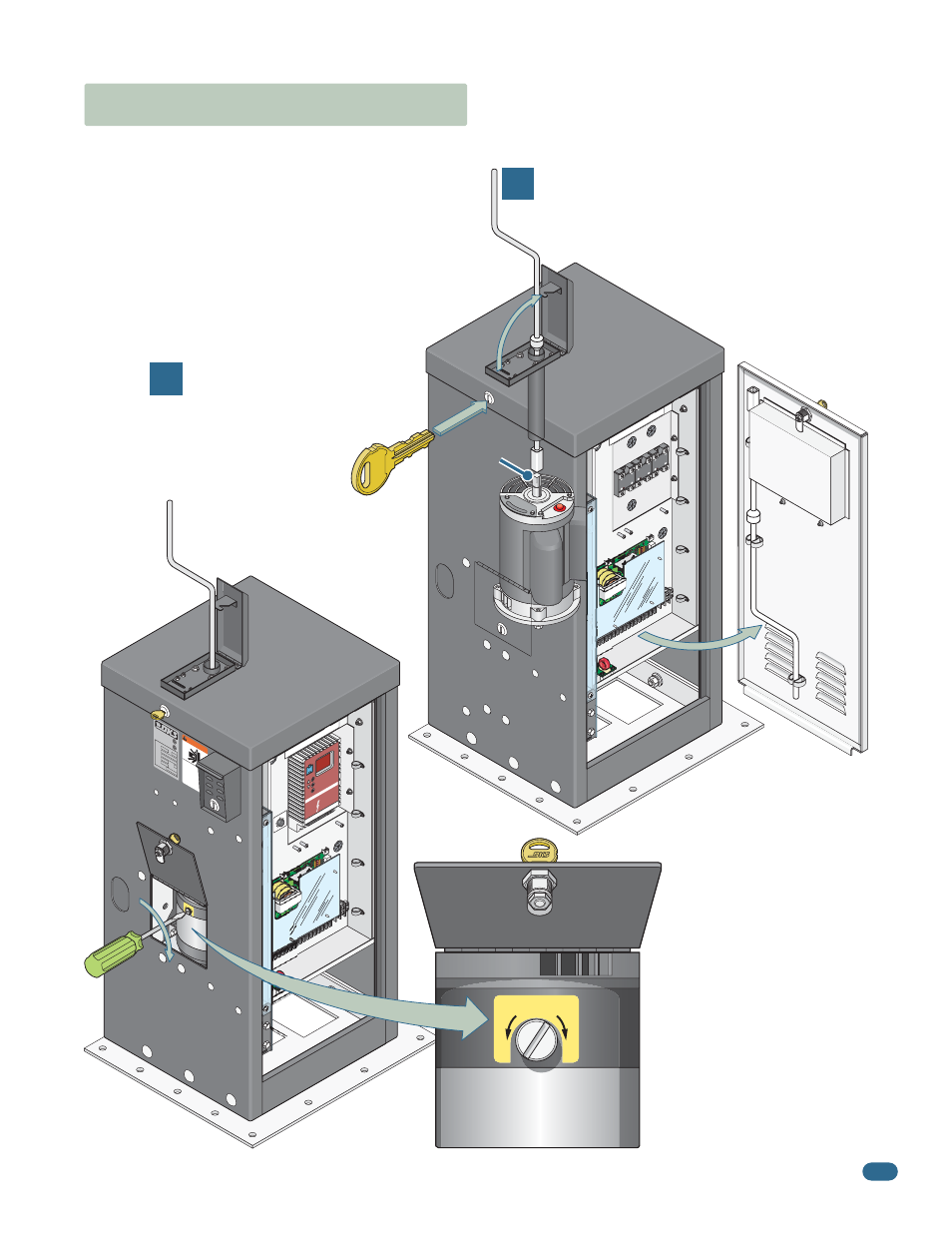
6.3 Manual Gate Operation
Caution:
Never attempt to manually operate any gate until you have verified that power to the operator has been shut-off.
Unlock Manual Crank
Access Panel
Cuts off AC power to the operator.
Manual Crank
9235, 9245
Mechanical Disc
Brake
The disc brake MUST be manually
released (disengaged) with a slotted
screwdriver (Not provided) before
manually operating the gate.
Disc brake will automatically
reengage after power has been
restored.
R E S E T
EXIT
LOOP
LMT
REVERSE
LOOP
REV SENSE
CLOSE
1
2
4
3
1
2
4
3
1
2
4
3
Manual Crank
Access Panel
Insert the supplied manual hand crank into the
access hole until it engages with the motor shaft.
Turn the crank to open the gate. 9235, 9245
mechanical disc brake model operators
MUST also have the disc brake
manually released before
manually cranking the
hand crank (See
below).
Motor
Shaft
Manual
crank in
stored
position.
Turn manual release
1/4 turn clockwise
to release the
disc brake.
MANUAL
RELEASE
R
E
S
E
T
R
E
L
E
A
S
E
MA
NUAL
REL
EAS
E
R
E
S
E
T
R
E
L
E
A
S
E
1
2
1
2
5
6
11
13A
13B
13E
25
16
17
L1
L2
L3
B-
B+
M
od
e
EPM
0 0 0
SCM
ser
ies
basi
c I/O
control
1 ft/s
.5
ft/s
0 ft/s
2 ft/s
1.5
ft/s
Disc
Brake
Access
Panel