1 main terminal description – Controlled Products Systems Group 9210-081 User Manual
Page 31
9210-065-F-4-12
29
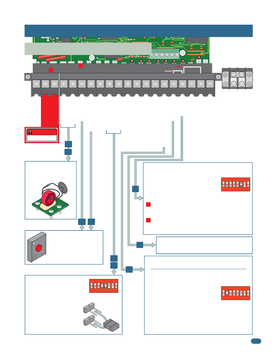
NC
NO
P7
20
19
19 18
18
17 16 15 14 13 12 11 10 9
8
7
6
5
4
3
2
1
Current Sensor
Current Sensor
Earth Ground
Motor Hot
Motor Neutral
Dr
y Relay Contact
Gate T
racker - Data
Gate T
racker - Busy
Entrapment Alarm
Alarm Reset
Full Open
Dr
y Relay Contact
24 V
A
C - 250 mamp. max.
Full Open
Partial Open
Standard Reverse OR Stop
Low V
o
ltage Common
Low V
o
ltage Common
Low V
o
ltage Common
Low V
o
ltage Common
3-Button Full Open
(DoorKing 3-Button Station ONL
Y)
3-Button Close
(DoorKing 3-Button Station ONL
Y)
4404
Operation of relay is dependent on
setting of SW 1, switches 4 and 5.
See page 20 and 21 for DIP-switch
function descriptions.
Relay contacts can be set for
Normally Open (NO) or Normally
Closed (NC) operation.
Contact rating is 1 amp maximum
at 24-volts DC.
NC
NO
DoorKing’s Remote alarm reset
station can be connected. See
page 31 for wiring.
It MUST be mounted in the
line-of-sight of the gate operator.
(DoorKing P/N 1404-080)
Used in conjunction with the
circuit board inherent
reversing sensors. See page
23 for further information.
DANGER
HIGH VOLTAGE!
5.1 Main Terminal Description
1
ON
23
45
6
7
8
SW 1 is Upside-Down on Board
1
ON
2
3
45
67
8
SW 1 is Upside-Down on Board
1
ON
23
45
67
8
SW 1 is Upside-Down on Board
This input ONLY fuctions when gate is fully opened or in the
closing cycle.
•
When gate is closing: SW 1, switch 7 is OFF, an input to
terminal #6 (eg: photo beam gets obstructed) will reverse and
open the gate.
Note: If the auto-close timer is ON, when
gate reaches the open position, timer will
not close the gate. Another input command
is needed to reset and close the gate.
•
When gate is closing: SW 1, switch 7 is ON, an input to
terminal #6 (eg: photo beam gets obstructed) will stop the
gate, then continue to close the gate when input is clear
(Used to help prevent tailgating vehicles from unauthorized
enrty). See page 21 for more information.
For long gate applications. An input device connected to
terminal #5 will open the gate to the partial open setting,
See page 22 for more information.
Auxiliary Common
Terminal
Connect any low
voltage common wire
to these 2 terminals.
#1 - Jumper Wire - SW 1, switch 3 OFF (Single Operator Exit Loop Partial Open)
#2 - Jumper Wire - SW 1, switch 3 OFF (Dual Operators Full Open)
16
17
11
12
15 14
6
4
5
SECTION 5 - MAIN TERMINAL WIRING
#1
Terminal #4 jumpered to terminal #5 will PARTIALLY open an
automatic exit loop using a single channel plug-in loop detector
installed in the exit loop port when using a single gate operator.
#2
Terminal #4 jumpered to terminal #2 will FULLY open
bi-parting gates using a dual channel plug-in loop detector
installed in the exit loop port when using dual gate operators.
•
SW 1, switch 3 is ON, terminal #4 functions as a normal FULL
open input. (Normal Setting). Single operator use ONLY.
•
SW 1, switch 3 is OFF, input to terminal #4
becomes the output from a plug-in loop
detector installed in the EXIT loop port of the
circuit board. A jumper wire is needed to open
and close the gate(s) for these applications: