6 chain installation – Controlled Products Systems Group 9210-081 User Manual
Page 18
9210-065-F-4-12
16
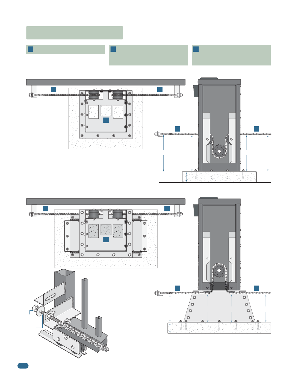
1.6 Chain Installation
Directly on a Concrete Pad - #1 Factory Set Idler Wheels
Heavy-Duty Pedestal Mounting Stand - #2 Lower Idler Wheel Position
Chain Bracket
Idler
Wheels
Idler
Wheels
Note: Be sure to follow all 3 guidelines. Installing the chain in any
other manner will cause excessive noise, chain idler wheel wear
and chain stretching.
10.5”
14”
14”
14”
14”
10.5”
10.5”
10.5”
Gate
Gate
Operator MUST be parallel to gate!
Chain brackets MUST align with
idler wheels so chain stays parallel
to gate!
Chain brackets MUST be mounted
so the chain remains the same
height as it is on the idler wheels!
1
1
1
2
2
2
2
2
3
3
3
3
3
Chain
Bracket
Chain
Bracket
Chain
Bracket
Chain
Bracket
Idler Wheels
Idler Wheels
Chain
Configuration
Chain
Configuration
Connect Chain Bracket
to Gate.
Weld completely
around bracket. Chain nut
and chain bolt should not
protrude past gate frame.
Connect Chain to Chain Bracket.
Connect chain to chain bolt
with master link. Adjust the chain nuts to tighten the chain. The
chain should sag no more than one (1) inch per 10 feet of travel.
Do not over tighten the chain.
Chain
Nut
Chain
Bolt
Chain Bracket
Option 2
Master Link
Option 1
Gate
Frame
Concrete Pad
4” Min.
Ground
Ground
Concrete Pad
4” Min.