3 loop detector wiring, Reverse loops, Automatic exit loop – Controlled Products Systems Group 9210-081 User Manual
Page 30: Exit loop por t reverse loop por t, Doorking plug-in loop detectors
9210-065-F-4-12
28
4404-010
TIME
DELA
Y
EXIT
LOOP
LMT
LMT
REVERSE
LOOP
REV SENSE
OPEN
REV SENSE
CLOSE
1
ON
23
4
1
ON
23
45
67
8
NC
NO
P8
P7
P6
20 19 18 17 16 15 14 13 12 11 10 9
8
7
6
5
4
3
2
1
Reverse Loop
Reverse Loop
Automatic Exit
Loop
4 Ft.
Min. to avoid gate
movement inter
ference.
4 Ft.
Min. to avoid gate
movement inter
ference.
4 Ft.
Min. to avoid
reverse loop inter
ference.
9410
Note: Loop detector
wiring is shown for
DoorKing plug-in
loop detector P/N
9410-010 (Single
Channel). If other
loop detectors are
used, refer to the
installation
instructions
supplied with those
detectors for wiring
and separate power
instructions.
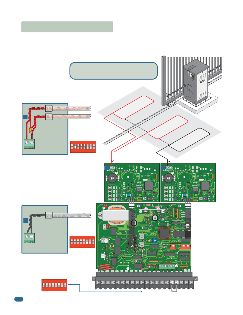
Reverse Loops
Reverse loops are placed on each side of the gate to
prevent the gate from closing on a vehicle in the gate’s
path. They will stop or reverse the cycling of the gate
while a vehicle is in or near the gate’s pathway.
9410
Single Channel
Single Channel
4.3 Loop Detector Wiring
Loop Lead In Wire
Loop Lead In Wires
DoorKing
Plug-in
Loop Detectors
Note: SW 1, switch 7 must
be set for the reverse loops.
See page 21 for more
information about SW 1,
switch 7 ON/OFF options.
A
B
Reverse loop
lead-in wires are
twisted approx.
6 twists per foot
and are wired in
series.
A
LOOP 1
W
AR
NI
NG
MO
VIN
G G
AT
E C
AN
CA
USE
Op
era
te g
ate
on
ly w
hen
ga
te a
rea
is i
n s
igh
t
and
fre
e of
pe
ople
an
d o
bs
tru
ctio
ns.
Do
no
t all
ow
ch
ildre
n to
pla
y in
ga
te a
rea
or o
per
ate
ga
te.
Do
no
t sta
nd i
n g
ate
pa
th o
r w
alk
thro
ugh
path
w
hile
ga
te is
m
ovin
g.
Rea
d o
wn
er’s
m
anu
al a
nd s
afe
ty in
stru
ctio
ns.
SERI
OUS
INJ
URY
OR DE
ATH
CLA
SS
CER
TIF
IED
TO
CA
N/C
SA
C
22.
2 N
O. 2
47
CO
NF
OR
MS
TO
AN
SI/U
L-3
25
VE
HIC
UL
AR
GA
TE O
PER
ATOR
HP
53
382
MO
DE
L
SER
IAL
VO
LTS
PH
AS
E
AM
PS
60 H
z
MA
X G
ATE
LO
AD
Doo
rK
ing
, In
c.,
Ing
lew
ood
, C
A
PVC Conduit
Automatic Exit Loop
Automatically opens the gate for exiting
vehicles without having to use a transmitter or
keypad. The exit loop can be placed a
minimum of 4 feet away from the reverse loop
or far enough away from the gate so the gate
has started opening or even completely opened
by the time you drive up to it (Free exit).
To help protect the operator from accidentally closing on vehicles in the gate’s path, DoorKing highly recommends that loops
and loop detectors be installed. Loops are laid underneath, cut into asphalt or concrete driveways or buried beneath gravel and
earth driveways. A loop detection system will sense a vehicle like a metal detector and send a signal to the gate operator
preventing the gate from automatically opening or closing on a vehicle when it is in the gate’s path. DoorKing recommends that
a licensed installer perform this work.
B
LOOP 1
PVC Conduit
DoorKing offers a free “Loop and Loop-Detectors
Information Manual” PDF located at DoorKing’s
web site for more information.
www.dkaccess.com
Exit loop lead-in
wires are twisted
approx. 6 twists
per foot.
Exit Loop Por
t
Reverse Loop Por
t
1
ON
23
45
6
7
8
SW 1 is Upside-Down on Board
1
ON
2
3
45
67
8
SW 1 is Upside-Down on Board
1
ON
2
3
45
67
8
SW 1 is Upside-Down on Board
Note: The plug-in exit loop detector can be
wired to partially open the gate if SW 1,
switch 3 is turned OFF. A jumper wire must
be connected from terminal #4 to terminal
#5 (See next page for more information).
Exit Loop Partial Open
SW 1, switch 3
must be ON to
FULLY open gate
(Normal function).