3 limit switches, Adjust limit nuts, Push – Controlled Products Systems Group 9210-081 User Manual
Page 24: Ac a1 c1, Limit leds, Partial open feature
9210-065-F-4-12
22
4404-010
TIME
DELA
Y
EXIT
LOOP
LMT
LMT
REVERSE
LOOP
REV SENSE
OPEN
REV SENSE
CLOSE
1
ON
23
4
1
ON
23
45
67
8
NC
NO
P8
P7
P6
20 19 18 17 16 15
14 13 12 11 10 9
8
7
6
5
4
3
2
1
Limit Nut
A
A1
C1
B
C
Limit LEDs
C
L
C
C
C
C
A
A
A
A
A
A
A
A
A
A
A
MT
T
T
T
T
T
T
T
T
L
L
L
L
T
L
L
L
L
L
T
L
L
L
L
L
L
T
L
L
L
L
L
L
L
T
L
L
L
L
LLMT
T
L
L
L
L
LMT
T
L
L
LMT
T
L
LMT
T
Note: If limit
plug is not
connected to
the circuit
board and
AC power is
turned on,
alarm will
sound and
operator will
NOT
function.
Main Terminal Partial Open Connection
Push
Push
L
ock-Plate
Limit Nut
A
B
C
A
C
C
C
C
Slow-Down
Limit
Slow-Down Limi
t
A1
C1
Partial Open Adjustment Rail
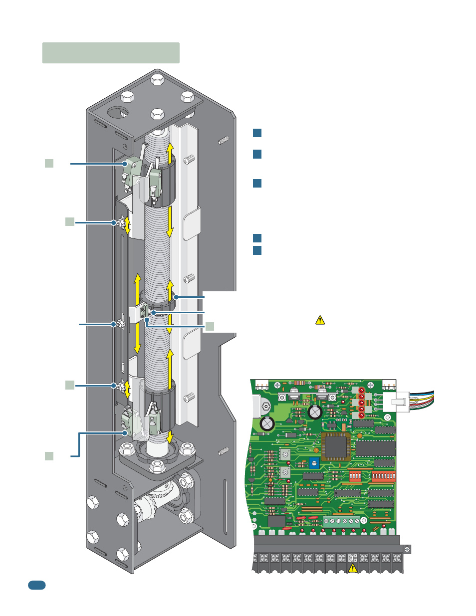
3.3 Limit Switches
Adjust Limit Nuts
Important:
Turn power OFF and set AC module (On select
models) to maximum speed before adjusting limit nuts!
Limit Nut
Push and hold the lock plate down where shown to adjust the
Open and Close limit nuts.
After adjusting the limit nuts, be sure that the lock-plate is
engaged in the slots on the limit nuts to prevent them from
rotating.
On select 9200 models, the slow-down limit assembly will
move up or down 3/4 inch. DO NOT remove the slow-down
limit assembly from the 3/4 inch slot and re-attach it in the
partial open adjustment rail to gain further adjustment. This
will cause mechanical damage to the switch assembly
when the operator is activated.
Turn power on and activate the gate operator.
Re-adjust the limit nuts as necessary for full-open and
full-close gate travel. After you are satisified with the gate
limit settings, the AC module (On select models) can then be
adjusted to personal preference (See page 24).
1
2
4
5
3
Partial Open Feature:
When using the
partial open feature, the operator’s access
control device must be connected to terminal
#5 . Adjust the middle limit nut and
magnetic pick-up sensor assembly to the
gate’s desired stopping position. Be sure to
align the magnet (Recessed in the limit nut)
with the magnetic pick-up sensor.
Slow-Down
Limit
(3/4 inch
adjustment
ONLY)
Slow-Down
Limit
(3/4 inch
adjustment
ONLY)
Partial Open
Magnetic
Pick-up
Sensor
Adjustment
Limit
Switch
Limit
Switch
A
C
A1
C1
Middle Limit Nut
Magnet - Align with pick-up sensor
Magnetic Pick-Up Sensor
B
Check the polarity of “Three Phase” operator ONLY: Position the gate half
way open. Give open command and while gate is opening, activate the
appropriate limit switch with your finger. Gate should STOP. If it does not,
activate the other limit switch. If this STOPS the gate, AC power wires must
be changed (Reverse the connection of any 2 wires and re-check limits).