2 continued, Switch definitions, Sw 2 - left 4 switches – Controlled Products Systems Group 9210-081 User Manual
Page 23: Sw 1 - right 8 switches
9210-065-F-4-12
21
3.2 Continued
Switch 1
This switch is a self-test feature that checks various functions of the circuit board and is used for bench test only.
Do not run this test with the operator connected to the gate.
Switch 2
Set to the OFF position for normal operation. Set to the ON position if gate OPENS in an UPHILL direction.
Switch 3
Set to the OFF position for normal operation. Set to the ON position if gate OPENS in an DOWNHILL direction.
Switch 4
Spare switch, leave in the OFF position.
SW 2 - Left 4 Switches
SW 2 is Upside-Down on Circuit Board.
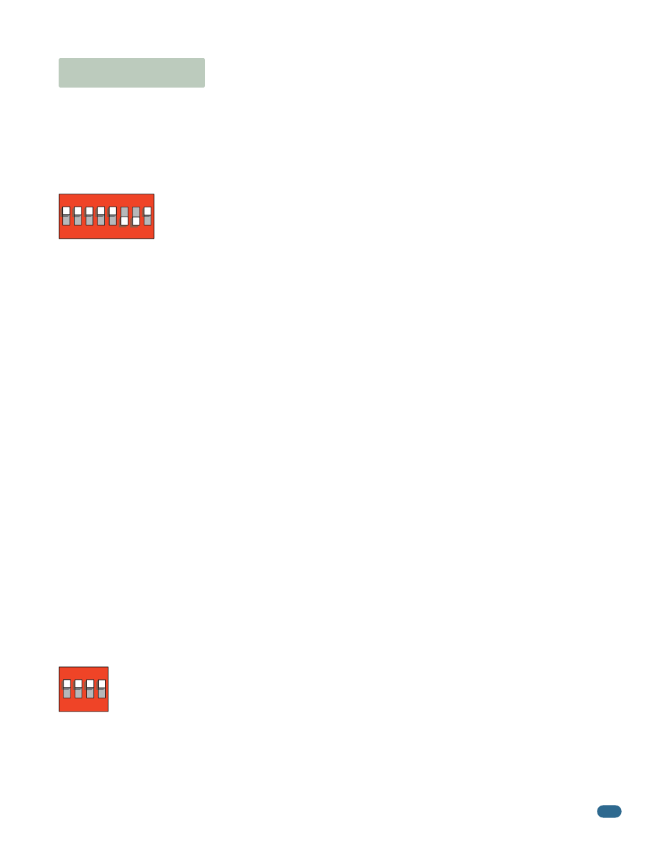
SW 1 - Right 8 Switches
SW 1 is Upside-Down on Circuit Board.
The two DIP-switches located on the circuit board (Upside-Down ) are used to program the operator to operate in various
modes and to turn on or off various operating features. Whenever a switch setting is changed, power to the operator must be
turned OFF and then turned back on for the new setting to take affect. Check and review ALL switch settings prior to applying
power to the operator.
Switch Definitions
1
ON
23
45
67
8
1
ON
23
4
Typical Settings
Typical Settings
Switch 1
Motor direction switch - Must OPEN the gate upon initial AC power up and open command. If the open command
begins to close the gate, turn AC power off and reverse this switch.
Switch 2
Turns the auto-close timer on or off. Can be adjusted from 1 to 23 seconds to close gate.
Switch 3
A device wired to terminal #4 (Switch 3 ON) is a normal full open input. The output wired to terminal #4 (Switch 3
OFF) becomes the output of a plug-in loop detector that is installed in the EXIT loop port of the circuit board (Which must be
installed for the “OFF” setting to function). A jumper wire is needed to open and close gate(s). Terminal #4 jumpered to #5 is
used for partially opening an automatic exit loop using a single channel plug-in loop detector for a single gate operator (Page
28) OR terminal #4 jumpered to #2 will fully open bi-parting gates using a dual channel plug-in loop detector (Page 32).
Switches 4-5
These work in conjunction with each other and determine when the relay on the board will be activated. This relay
can be used as a switch for various functions such as illuminating a warning light when the gate is moving, or turning on a
green light when the gate is full open. If a magnetic lock is used with the gate operator, these switches must be set for magnetic
lock operation which limits the relay to activate only when the gate is opening and full open.
Switch 6
Warn Before Operate, When set to the ON position, the internal alarm in the operator will start sounding 2-3 seconds
prior to the gate starting and continue throughout the gate’s cycle.
Switch 7
Determines if an input to terminal #6 (Photo Sensors) AND/OR reverse loops will reverse OR stop a CLOSING gate.
A tailgating vehicle can activate terminal #6 (Photo sensors) and/or reverse loops while the gate is in the closing cycle from the
previous vehicle’s authorized entry:
If switch 7 is turned OFF (Reverse), the closing gate that gets activated by a tailgating vehicle will reverse back to the open
position, possibly allowing the tailgating vehicle unauthorized entry while the gate is reversing back to the open position.
If switch 7 is turned ON (Stop), the closing gate that gets activated by a tailgating vehicle will stop, partially or completely
blocking the pathway, NOT allowing the tailgating vehicle to enter without proper authorization. The gate will not move until all
sensors are clear, usually forcing the tailgating vehicle that activated the sensors to back away from the gate. The gate will then
continue until closed, helping prevent the tailgating vehicle from unauthorized entry.
Switch 8
Turning the quick-close feature on will cause the auto close timer to close the gate after 1 second, regardless of the
setting of the auto close timer potentiometer. This will also cause an opening gate to stop and reverse when the reverse loops
and/or photo sensors are cleared. This feature, along with turning switch 7 ON above, is useful to help prevent tailgating
vehicles from unauthorized entry.