2 secondary entrapment protection device locations, Non-secure side, Secure side – Controlled Products Systems Group 9210-081 User Manual
Page 28
9210-065-F-4-12
26
TIME
DELA
Y
EXIT
LOOP
LMT
LMT
REVERSE
LOOP
REV SENSE
OPEN
REV SENSE
CLOSE
1
ON
23
4
1
ON
23
45
67
8
NC
NO
P8
P7
P6
4404-101
20 19 18 17 16 15 14
13
12 11 10 9
8
7
6
5
4
3
2
1
Gate Frame
or Less
or Less
Non-Secure Side
Outside Property
Secure Side
Inside Property
Filler Post or Barrier
Reversing Edge (Open Contact Sensor)
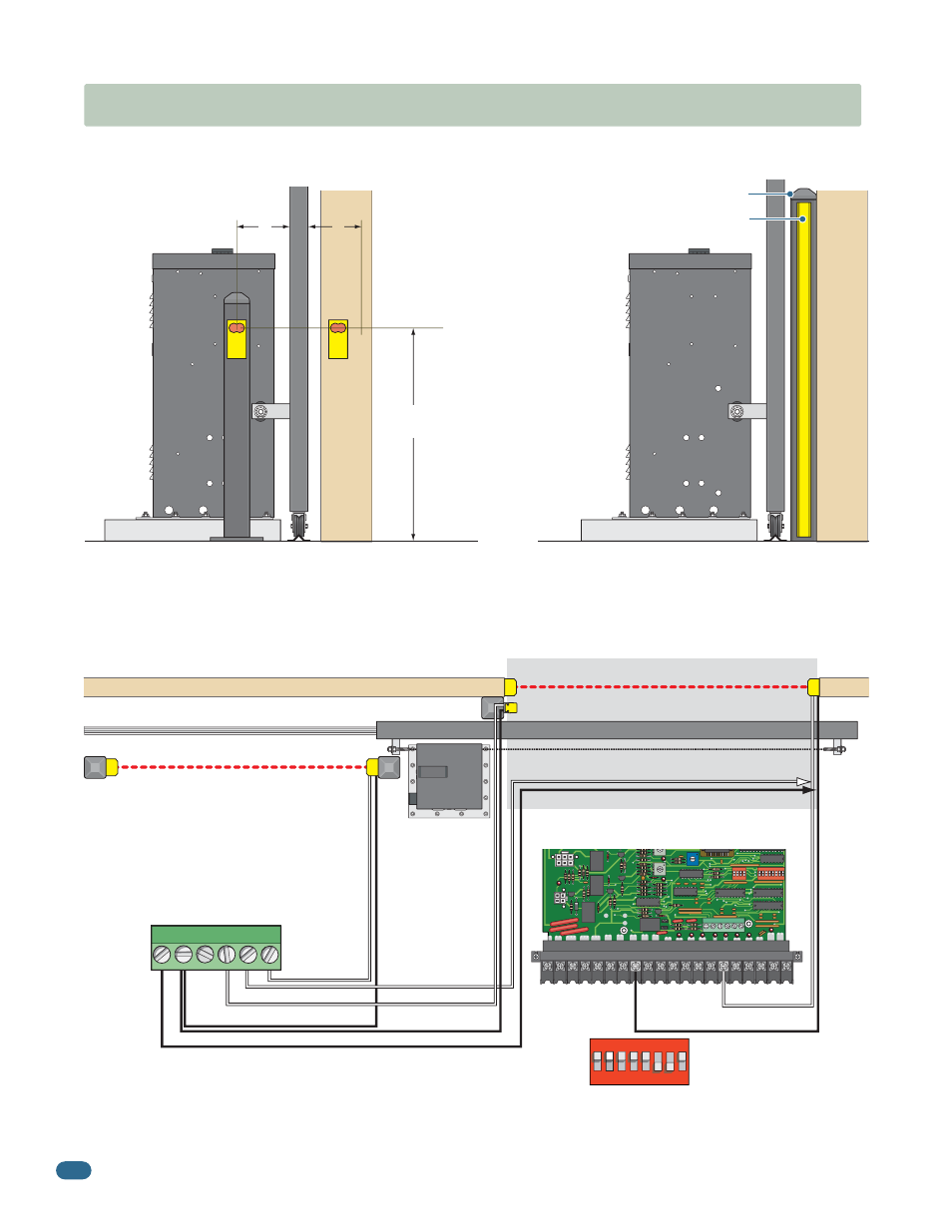
4.2 Secondary Entrapment Protection Device Locations
Photo Sensors (With Filler Post and Reverse Edge) Sample Setup
Typical UL Photo Sensor mounting height
and distance away from gate.
Photo sensors may be installed on either side of gate frame.
5”
21”
Typical
If the distance between the gate
and wall is greater than 2 1/4”.
Wall
UL sensor mounted on post.
UL sensor mounted on wall.
Closed Gate
Wall
Normally Open
Normally Open
Normally Open
Common
Common
Common
Common
Normally Open
A filler post or barrier may need to be installed between the
gate and wall area to reduce the distance to 2 1/4” or less.
A reversing edge should be installed on the post or barrier
for safety (See page 8 for more information).
Photo Sensor Power Note: Photo sensors can be powered by the built-in
convenience outlets located on the operator (See previous page).
Closing-direction photo sensors wired to UL 325 terminal.
Closing-Direction Photo Beam
Opening-Direction Photo Beam
6-Pin
UL 325
Terminal
Wiring
“Reverse” Closing-Direction Option
Filler Post with Opening-Direction Reversing Edge (If necessary, see above)
OPEN Entrapment Sensor
CLOSE Entrapment Sensor
OPEN Contact Sensor
CLOSE Contact Sensor
Low V
oltage Common
Low V
oltage Common
SW 1, switch 7
MUST be OFF.
IF the closing-direction photo sensor is wired to the UL 325 terminal, a
closing-direction photo beam that gets obstructed will STOP the gate, then
resume closing the gate when the obstructed photo beam has been cleared.
IF the closing-direction photo sensor is wired to the #6 main
terminal, a closing-direction photo beam that gets
obstructed will REVERSE the gate back to the open position.
Gate Frame
5”
1
ON
23
45
6
7
8
SW 1 is Upside-Down on Board
1
2
3
4
5
6