7 installation of warning signs, 1 high voltage wire runs, This gate operator must be properly grounded – Controlled Products Systems Group 9210-081 User Manual
Page 19: Typical grounding sources, Wire size / distance in feet
9210-065-F-4-12
17
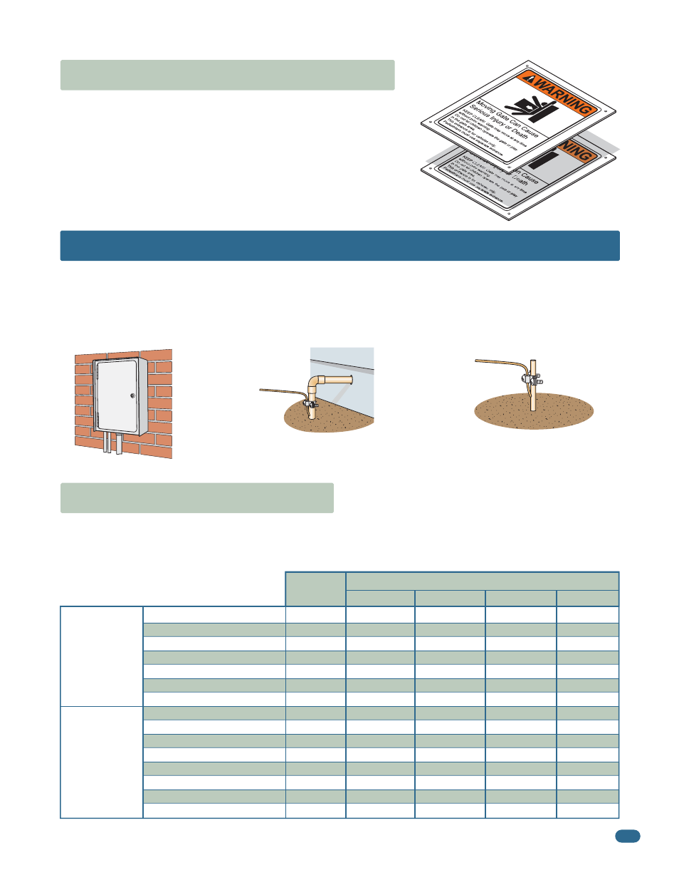
1.7 Installation of Warning Signs
This DoorKing Slide Gate Operator is shipped with two warning signs. The purpose
of the warning sign is to alert uninformed persons, and to remind persons familiar
with the gate system, that a possible hazard exists so that appropriate action can
be taken to avoid the hazard or to reduce exposure to the hazard. See page 9 for
typical placement of signs.
•
Permanently install the supplied warning signs in locations so
that the signs are visible by persons on both sides of the gate.
•
Use appropriate hardware such as wood or sheet metal screws
(not supplied) to install the warning signs.
2.1 High Voltage Wire Runs
The 9200 draws significant power and each operator should have a “Dedicated” circuit breaker at the power source. If power wiring is
greater than the maximum distance shown, it is recommended that a service feeder be installed. When large gauge wire is used, a separate
junction box must be installed for the operator connection. The wire table is based on stranded copper wire. Wire run calculations are based
on the NEC recommended maximum 3% voltage drop on the power line, plus an additional 10% reduction in distance to allow for other losses
in the system.
Wire Size / Distance in Feet
Amps
12 AWG
10 AWG
8 AWG
6 AWG
9210 Single 1 HP: 115 VAC
9210 Single 1 HP: 208 VAC
9210 Single 1 HP: 230 VAC
9220 Single 2 HP: 208 VAC
9220 Single 2 HP: 230 VAC
9245 Single 3 HP: 208 VAC
9245 Single 3 HP: 230 VAC
9210 Single 1 HP: 208 VAC
9210 Single 1 HP: 230 VAC
9220 Single 2 HP: 208 VAC
9220 Single 2 HP: 230 VAC
9230, 9240 Single 3 HP: 208 VAC
9230, 9240 Single 3 HP: 230 VAC
9235 Single 3 HP: 208 VAC
9235 Single 3 HP: 230 VAC
Single Phase
Three Phase
SECTION 2 - AC POWER TO OPERATOR(S)
Before attempting to connect any wiring to the operator, be sure that the circuit breaker in the electrical panel is in the OFF position. Perma-
nent wiring must be installed to the operator as required by local electrical codes. It is recommended that a licensed electrical contractor
perform this work.
Since building codes vary from city to city, we highly recommend that you check with your local building department prior to installing
any permanent wiring to be sure that all wiring to the operator (both high and low voltage) complies with local code requirements.
THIS GATE OPERATOR MUST BE PROPERLY GROUNDED!!
110
390
440
165
180
150
170
680
730
340
400
225
255
177
195
175
620
700
270
290
240
270
1090
1170
545
640
365
415
280
315
295
1040
1170
450
490
400
450
1815
1950
905
1070
610
690
465
525
440
1560
1760
675
735
600
680
2720
2920
1360
1605
915
1035
700
790
9.7
5.0
4.9
11.5
11.7
12.8
12.6
3.3
3.4
6.6
6.2
9.8
9.6
12.8
12.6
Never run low voltage rated wire insulation in the
same conduit as high voltage rated wire insulation.
Typical Grounding Sources
Ground to metallic cold water pipe.
Ground
Wire
Ground
Wire
Ground to existing electrical system.
Electrical
Panel
Grounding rod 10 feet in soil.
IMPORTANT:
Ground wire shown without
safety protection for clarity. Make sure
ground wire is protected from being
touched or electrical shock could occur!