4 bi-parting gates wiring - dual gate operators, Loop detector 3-wire receiver, Interconnection cable – Controlled Products Systems Group 9210-081 User Manual
Page 34: Primary operator, Secondary operator
9210-065-F-4-12
32
4404-010
4404-010
NC
NO
P7
20 19 18 17 16 15 14 13 12 11 10 9 8 7
6
5
4
3
2 1
1 2 3
4
5
6
UL 325
Terminal
UL 325
Terminal
UL 325
Terminal
UL 325
Terminal
Primary Operator
NC
NO
P7
20 19 18 17 16 15 14 13 12 11 10 9 8 7
6
5 4 3
2 1
1 2 3
4
5
6
UL 325
Terminal
UL 325
Terminal
UL 325
Terminal
UL 325
Terminal
Secondary Operator
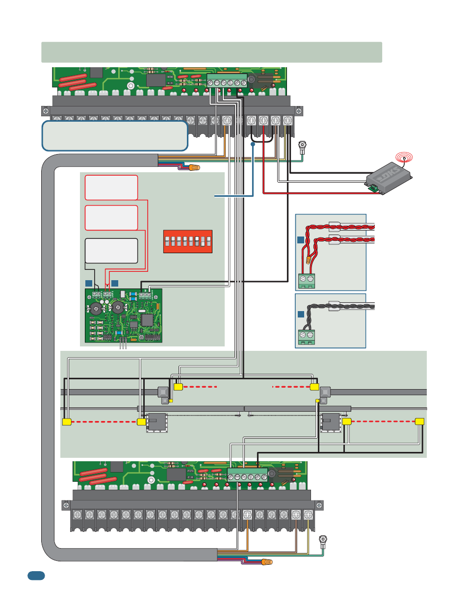
5.4 Bi-Parting Gates Wiring - Dual Gate Operators
Plug the DoorKing DUAL
channel loop detector
into Primary Operator’s
Exit Loop Port.
Dual Channel
9409
24 Volt Power
Relay
Com
Green to primary operator
chassis ground.
Com to #1
Normally Open to #6
Automatic
Exit Loop
Reverse
Loop
Reverse
Loop
Loop Lead-In Wires
Loop Detector
3-Wire Receiver
250 mamp. max.
•
Requires AC power to each operator.
•
Both operator DIP-switches must be set.
•
Connect all control devices, auxiliary
devices and loops to the primary
operator only.
Secondary Entrapment
Protection Devices
for Bi-Parting Gates
Secondary
Operator
Primary
Operator
To Close Photo #2
To Open Edge #3
To Open Edge #3
To Open Edge #3
To Common #5
To Common #5
To Open Photo #1
To Open Photo #1
Fence
Gate
Opening Non-Contact Sensor
Closing Non-Contact Sensor
Opening Contact Sensor
Opening Contact Sensor
Opening Non-Contact Sensor
Fence
Gate
Y
ellow
Brown
Orange
Gray
Green to secondary operator
chassis ground.
Y
ellow
Brown
Orange
Gray
Primary SW 1, switch 3
must be OFF.
Interconnection Cable
Sold separately from DoorKing.
5 wires used (8 - 18 A
W
G wires total).
•
Separate power source for photo sensors.
See page 25 for more information.
1
ON
2
3
45
67
8
SW 1 is Upside-Down on Board
When using plug-in
loop detector
Connect a jumper
from #4 to #2:
fully opens gates.
Filler Post if necessary (See page 8 for more info).
Note: Secondary operator ‘s
DIP-switches MUST be set for
the dual operators to cycle
correctly. See pages 20 and 21
for more information about dual
operator DIP-switch settings.
Note: 4-wire
radio receiver, or
any other
opening devices
get wired to
primary operator
ONLY, as shown
on page 30.
B
B
LOOP 1
Exit loop lead-in
wires are twisted
approx. 6 twists
per foot.
Reverse loop
lead-in wires are
twisted approx.
6 twists per foot
and are wired in
series.
A
A
LOOP 2
PVC Conduit
PVC Conduit
DoorKing offers a free “Loop and Loop-Detectors
Information Manual” PDF located at Doorking’s
web site for more information.
www.dkaccess.com