Auto-close timer, Dry relay contact, Dip-switches leds – Controlled Products Systems Group 9210-081 User Manual
Page 21: Inherent reverse sensors, Caution, Self-test, Ac module adjustment, Motor plug p6 mechanical disc brake plug p8, Limit switch plug p2, Nc no
9210-065-F-4-12
19
4404-010
TIME
DELA
Y
EXIT
LOOP
LMT
LMT
REVERSE
LOOP
REV SENSE
OPEN
REV SENSE
CLOSE
1
ON
23
4
1
ON
23
45
67
8
NC
NO
P8
P7
P6
20 19 18 17 16 15 14 13
12 11
10 9
8
7
6 5
4
3
2
1
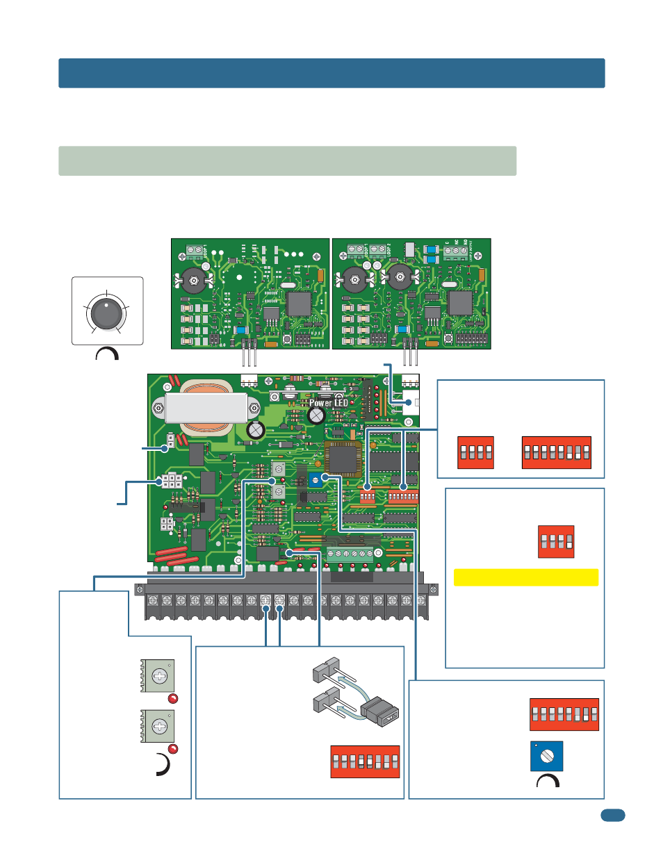
3.1 Circuit Board Description and Adjustments
SECTION 3 - ADJUSTMENTS
The switch settings and adjustments in this chapter should be made after your installation and wiring to the operator(s) is
complete. Whenever any of the programming switches on the circuit board are changed, power must be shut-off, and then
turned back on for the new setting to take effect.
Auto-close timer (when
turned on) SW 1, switch 2.
Dry relay contacts
(terminals 11-12) can be
set for Normally Open
(NO) or Normally Closed
(NC) operation by placing
the relay shorting bar on the
N.O. or N.C. pins respectively.
SW 1, switches 4 and 5 must
be set to control relay. See
next 2 pages for descriptions.
Auto-Close Timer
AC Module
Adjustment
9220, 9230, 9235,
9240 and 9245 models
Dual Channel Loop Detector
Single Channel Loop Detector
Dry Relay Contact
Set the DIP-switches on the circuit
board to the desired setting. See
switch descriptions on next 2 pages.
DIP-Switches
LEDs
Indicates that low voltage power is applied to the circuit board. Input LEDs should be OFF and will only
illuminate when the input is activated. Limit LEDs will be on when the respective limit switch is activated.
Adjust reversing
sensitivity for
open and close
directions.
Full counter
clockwise for
minimum
sensitivity, full
clockwise for
maximum
sensitivity.
See page 23.
Inherent
Reverse
Sensors
Motor
Plug P6
Mechanical
Disc Brake
Plug P8
9235 and 9245
models ONLY
Limit Switch Plug P2
Self-test (when turned on)
SW 2, switch 1.
CAUTION
Do not run self-test with the
operator connected to the gate.
The drive chain MUST be
disconnected before running the
self-test. This feature is designed
for bench testing ONLY.
Self-Test
UL 325 Terminal
Power LED
Exit Loop Port
Reverse Loop Port
LMT
Limit LEDs
Input LEDs
Input LED
Input LEDs
9410
9409
1
23
Adjust from 1 second
(full counter-clockwise) to
approximately 23 seconds
(full clockwise).
NC
NO
Min
Max
CLOSE
Sensitivity
OPEN
1 ft/s
.5 ft/s
0 ft/s
2 ft/s
1.5 ft/s
Min
Max
Speed
See page 24.
See page 24.
See page 32.
See page 28.
AC Module Dual
Adjustment
9235 models with
mechanical disc brake.
HIGH SPEED
ADJUST
SLOW SPEED
ADJUST
P1
P2
1495-010
1
ON
23
45
67
8
SW 1 is Upside-Down on Board
1
ON
23
4
SW 2 is Upside-Down on Board
1
ON
23
4
SW 2 is Upside-Down on Board
1
ON
2
34
56
78
SW 1 is Upside-Down on Board
1
ON
23
45
67
8
SW 1 is Upside-Down on Board