3 auxiliary terminal description, 4 auxiliary terminal wiring, Auxiliary terminal – Controlled Products Systems Group 6300-080 User Manual
Page 30
6300-065-Z-7-12
28
20
19
18
17
NC
NO
2
3
4
5
6
7
8
5.3 Auxiliary Terminal Description
20
19
18
17
16
15
14
13
12
11
10
9
8
7
6
5
4
3
2
1
NC
NO
1
ON
2
3
4
5
6
7
8
1
ON
2
3
4
5
6
7
8
1.
Alarm Output:
Provides power to activate the entrapment alarm.
2.
Alarm Reset Input:
Input to reset the operator after an entrapment alarm.
3. Common: Common for alarm output and alarm reset input.
4.
Tracker Data:
Supplies gate operator data to Tracker expansion board (P/N 2351-010). Refer to the Tracker Installation
and Wiring Manual for detailed information.
5.
Tracker Data:
Supplies gate operator data to Tracker expansion board (P/N 2351-010). Refer to the Tracker Installation
and Wiring Manual for detailed information.
6.
Tracker Data:
Supplies gate operator data to Tracker expansion board (P/N 2351-010). Refer to the Tracker Installation
and Wiring Manual for detailed information.
7.
Non-Contact Sensor (Photo Sensor Input):
This input will cause the gate operator to stop when activated in either the
opening or closing cycles. The gate operator will remain stopped until the photo-beam input is cleared, at which time the
operator will resume normal operation (See pages 23 and 24).
8.
Common:
Common for photo sensor input.
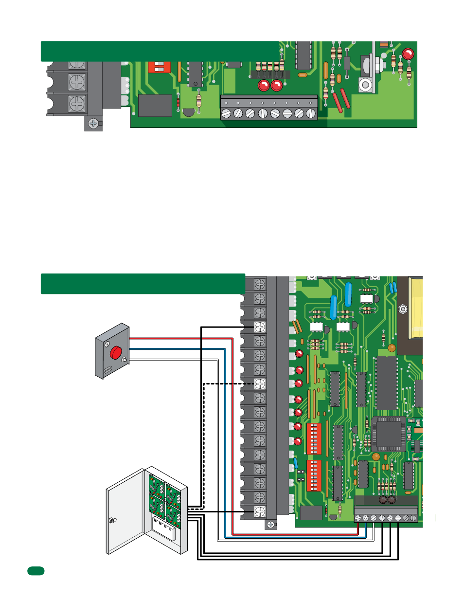
DoorKing Access Control System (Model 1833, 1835, 1837 or
1838) tracker system can be connected.
This system can keep track of gate operator cycle count, shorted
inputs, loop detector problems, any forced entry attempts, if the
gate has struck anything during the open or close cycle, power
interruptions, etc.
For more detailed information
refer to the Tracker
Installation and Wiring
Manual, DoorKing P/N
2351-010.
Terminal 11 required only
if the tracker board will
activate the gate
operator. Refer to the
manual 2351-065 for
detailed information.
1 2 3 4 5 6
8
7
Gate Tracker
(Quad Box Shown)
Red Alarm Output Terminal
Blue Alarm Reset Terminal
White Common Terminal
1
8
7
6
5
4
3
2
Remote Alarm Reset Station
(DoorKing P/N 1404-080 Only)
MUST be mounted in the line-of-sight
of the gate operator.
4502
4502
Auxiliary Terminal
Tracker LEDs
5.4 Auxiliary Terminal Wiring
Auxiliary Terminal