Photo sensors sample setup – Controlled Products Systems Group 6300-080 User Manual
Page 26
6300-065-Z-7-12
24
Non-Secure Side
Outside Property
Secure Side
Inside Property
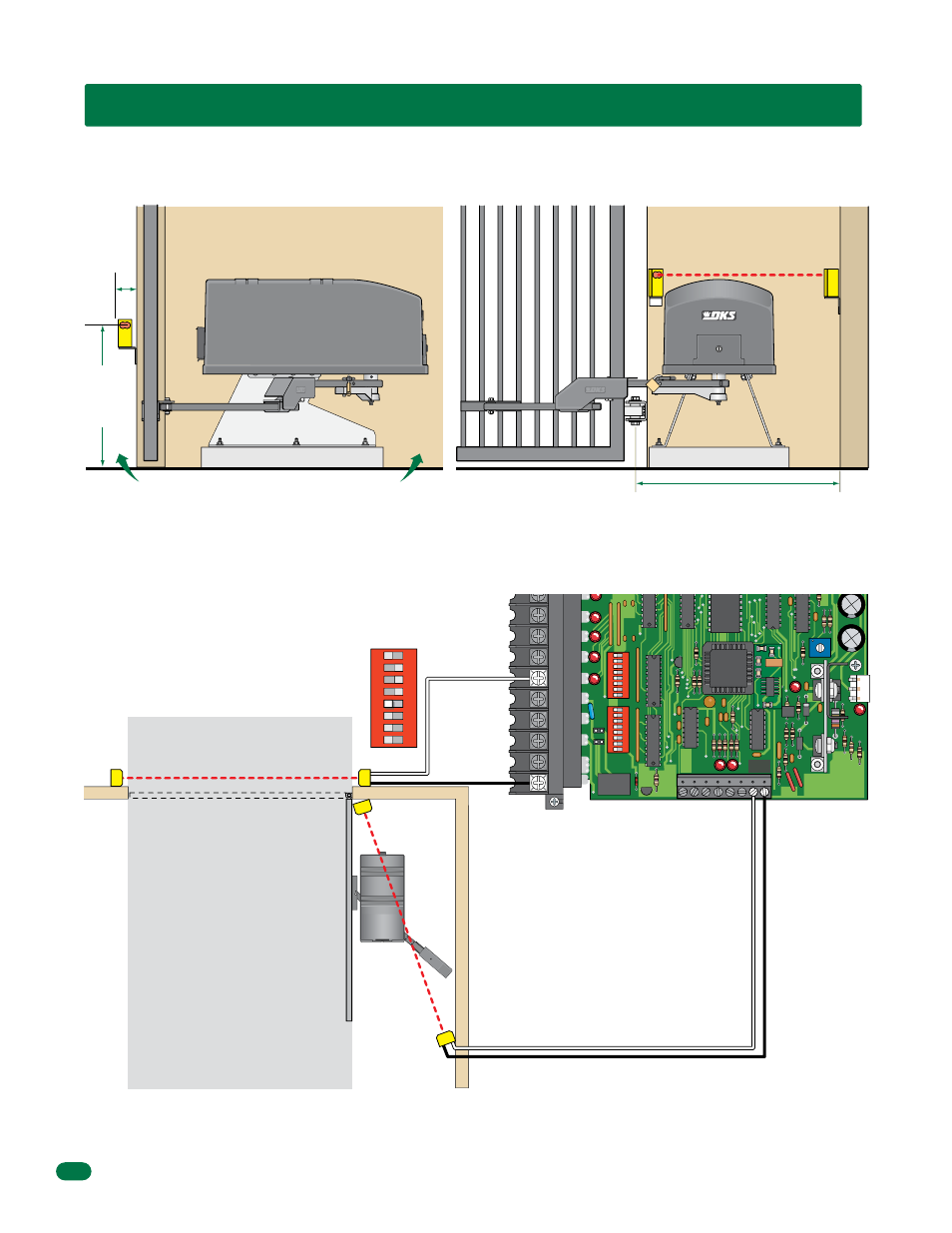
4.2 Entrapment and Safety Protection Device Locations
Photo Sensors Sample Setup
Typical UL Photo Sensor mounting height and distance away from gate.
Opening-Direction Photo Sensors
Closing-Direction Photo Sensors
W
all
UL sensor mounted just
above top of operator
Common
Common
Normally Open
Normally Open
SW 2
1
ON
2
3
4
5
6
7
8
SW 2, switch 5
MUST be OFF.
If this space is less than
16 inches, secondary
entrapment protection is
required in this area.
5” or
Less
Gate Frame (Closed)
Gate Frame (Closed)
21”
Typical
27.5”
Max.
Opening-Direction
Photo Beam
Photo Sensor Power Note: Photo sensors can be powered by Model 6300.
See previous page for the built-in 115 VAC convenience outlets location.
This diagram is for illustration purposes. The actual
placement of the protection devices is dependent on
the specific installation requirements.
Wall
Closing-Direction Photo Beam
Opened Gate
Closed Gate
20
19
18
17
16
15
14
13
12
11
NC
NO
1
ON
2
3
4
5
6
7
8
1
ON
2
3
4
5
6
7
8
7 8
4502
Auxiliary Terminal
Main Terminal