3 dip-switch sw 2 settings, Sw 2 (bottom 8 switches) – Controlled Products Systems Group 6300-080 User Manual
Page 22
6300-065-Z-7-12
20
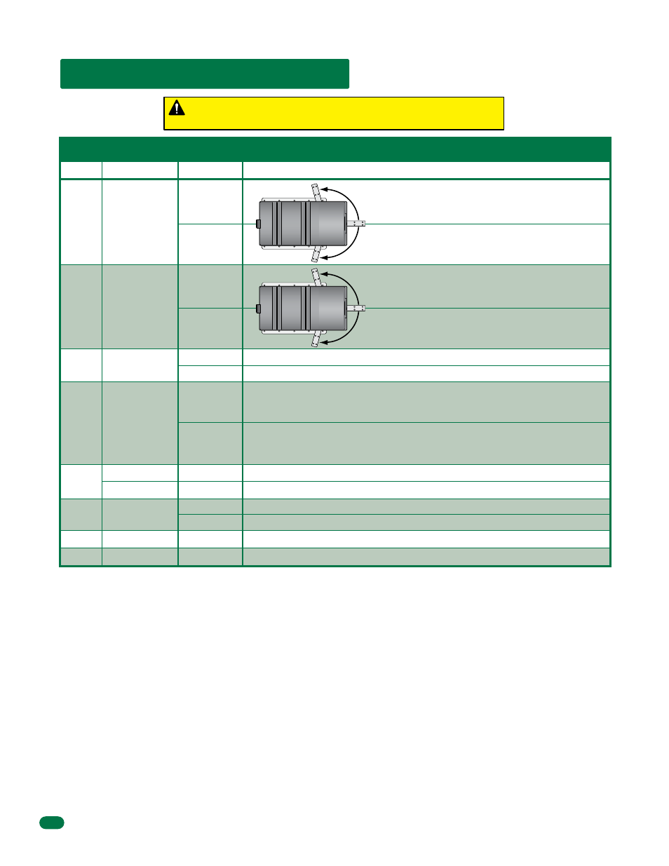
3.3 DIP-Switch SW 2 Settings
Switch 1
Must OPEN the primary operator’s gate upon initial AC power up and open command. If the FIRST open command
begins to close the gate, turn AC power off and reverse this switch.
Switch 2
Must OPEN the secondary operator’s gate upon initial AC power up and open command. If the FIRST open command
begins to close the gate, turn AC power off and reverse this switch. This switch will be set the opposite of switch 1 (e.g. If
switch 1 is OFF, then switch 2 will be ON).
Switch 3
This switch is a self-test feature that checks various functions of the circuit board and is used for bench test only.
Do not run this test with the operator connected to the gate.
Switch 4
This switch applies high voltage motor power to the secondary operator motor terminal located at the top of the board
(See page 17). If a primary / secondary system is in use, this switch should be ON and the secondary motor wires connected to
the secondary operator motor terminal. For single gate applications, this switch can be turned OFF.
Switch 5
This switch sets the input at Terminal 15 to act as a normal reverse input OR to act as a shadow input. A shadow input
will only hold the gate operator in the open position once it is in the full open position. A shadow input will not reverse the
direction of the gate operator once it begins its close cycle.
Switch 6
Used in primary / secondary applications, turning this switch ON will cause the secondary operator to start 1-2
seconds before the primary operator. This allows the secondary gate to reach the full closed position before the primary gate,
which is desirable when the gates are constructed with an overlap or if a magnetic lock is used to secure the gates.
Switches 7 and 8
Spare switches, leave in the OFF position.
OFF
ON
Reverse Loop
Shadow Loop
Terminal 15 is a normal Reverse input.
Terminal 15 is a Shadow input. Gate will NOT stop during the close cycle.
Switch
Function
Setting
Description
SW 2 (Bottom 8 Switches)
Secondary
Operator
Opening
Direction
OFF
ON
OFF
ON
OFF
ON
Self-Test
Motor Control
for Secondary
Operator
Primary
Operator
Opening
Direction
2
3
4
6
1
Normal Setting. Normal operation.
Self-test mode. Operator MUST be disconnected from gate to run self test.
Switch is OFF when both primary and secondary operator motors are powered
from main terminals 4 and 5. Applies to operators originally manufactured with
4501, Rev O boards or lower).
Switch is ON when secondary operator motor is powered from the secondary
motor terminals. Applies to operators manufactured with 4501, Rev P boards and
higher, and all 4502 boards.
5
7
8
Gate Overlap
Not Used
Not Used
OFF
ON
OFF
OFF
Primary and secondary operators start at the same time.
Secondary operator starts 1-2 seconds prior to primary operator.
Leave in the OFF position.
Leave in the OFF position.
OFF
ON
Opens Counter-Clockwise using OFF setting.
Opens Clockwise using ON setting.
Opens Counter-Clockwise using OFF setting.
Opens Clockwise using ON setting.
Every time the operator is powered up, the First open command will
automatically set the open and close limits of the gate. (See page 21).