Operator output shaft – Controlled Products Systems Group 6300-080 User Manual
Page 12
6300-065-Z-7-12
10
SECTION 1 - INSTALLATION
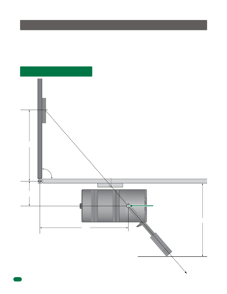
1.1 Operator Position
35”
90°
Open Gate
Closed Gate
Gate Bracket
Operator
Output Shaft
An imaginary straight line drawn from the closed
gate bracket through the open gate bracket MUST
intersect the operator output shaft.
This layout is for the pad or post mount
with the gate opening 90°.
See Section 1.9 for gate’s opening wider than 90°.
Minimum distance required
for arm clearance in the
open position.
Note: The operator can be placed further away from the open gate than
shown as long as the imaginary straight line drawn from the closed gate
bracket through the open gate bracket intersects the operator output shaft.
34”
12”
43”
Prior to beginning the installation of the swing gate operator, we suggest that you become familiar with the
instructions, illustrations, and wiring guide-lines in this manual. This will help insure that your installation is
performed in an efficient and professional manner compliant with UL 325 safety and ASTM F2200 construction
standards.
The proper installation of the vehicular swing gate operator is an extremely important and integral part of the
overall access control system. Check all local building ordinances and building codes prior to installing this
operator. Be sure your installation is in compliance with local codes.