2 high voltage terminal connections, 115 vac models, This gate operator must be properly grounded – Controlled Products Systems Group 6300-080 User Manual
Page 18
6300-065-Z-7-12
16
High Voltage
Conduit
High Voltage Conduit
Chassis
Ground
Neutral
115 V
A
C (Hot)
115 VAC Models
230/460 V
A
C
230/460 V
A
C
115 V
A
C Neu
115 V
A
C Neu
115 V
A
C Hot
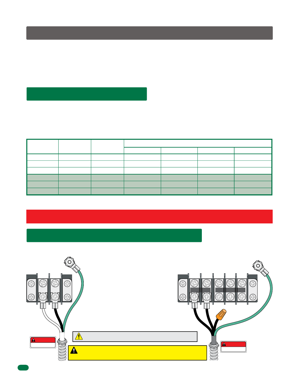
2.2 High Voltage Terminal Connections
230 and 460 Volt 3-phase
input, use only two legs of the
incoming 3-phase power.
230 VAC/460 VAC Models
DANGER
HIGH VOLTAGE!
DANGER
HIGH VOLTAGE!
Chassis
Ground
2.1 High Voltage Wire Runs
SECTION 2 - AC POWER TO OPERATOR(S)
Before attempting to connect any wiring to the operator, be sure that the circuit breaker in the electrical panel is in the OFF
position. Permanent wiring must be installed to the operator as required by local electrical codes. It is recommended that a
licensed electrical contractor perform this work.
Since building codes vary from city to city, we highly recommend that you check with your local building department prior
to installing any permanent wiring to be sure that all wiring to the operator (both high and low voltage) complies with local
code requirements.
THIS GATE OPERATOR MUST BE PROPERLY GROUNDED!!
The distance shown in the chart is measured in Feet from the operator to the power source. If power wiring is greater than the
maximum distance shown, it is recommended that a service feeder be installed. When large gauge wire is used, a separate
junction box must be installed for the operator connection. The wire table is based on stranded copper wire. The wire run
calculations are based on a power source with a 3% voltage drop on the power line, plus an additional 10% reduction in
distance to allow for other losses in the system.
“Optional” 3.3 Amp Heater Installation Note: When installing the heater(s), refer to the “high voltage AC power wire size and
distance requirements” table on the instruction sheet with the heater kit (P/N 1601-154) for AC power wire run requirements.
This table illustrates the high voltage wire size and distance requirements for a single operator.
Reduce the wire distance in half for a primary/secondary dual gate operator application
Model
Type
Voltage
Required
Amps
Required
Wire Size / Distance in Feet
12 AWG
10 AWG
8 AWG
6 AWG
Never
run low voltage rated wire insulation in the same conduit as high voltage rated wire insulation.
180
715
3075
100
395
1550
5.4
2.7
1.4
9.7
4.9
2.5
115
230
460
115
230
460
290
1150
4435
162
630
2480
485
1915
7390
270
1055
4140
725
2875
11,085
405
1580
6210
6300 1/2 HP
6300 1/2 HP
6300 1/2 HP
6300 1 HP
6300 1 HP
6300 1 HP
Section 1 MUST be completed before power can be turned on.
Every time the operator is powered up, the First open command will
automatically set the open and close limits of the gate. (See page 21).
• Route incoming high voltage power through
underground conduit and into the operator as
shown in Section 1.4 or 1.5 on page 12 or 13.
• Be sure wiring is installed in accordance with
local codes. Be sure to color code all wiring.
• It is recommended that a surge suppressor be
installed on the high voltage power lines to help
protect the operator and circuit board from
surges and power fluctuations.
• Secondary operator in a dual operator application
gets power through the 8-wire interconnection
cable that links the 2 operators together.
See Section 2.3 “Bi-Parting Gates Wiring - Dual
Gate Operators” on the next page.
Output
Input
VERIFY AC input power MATCHES your
specific operator power BEFORE wiring!
DO NOT connect 460 VAC input power
to a 230 VAC operator,
damage will occur and VOID warranty.