4 automatic open / close limit adjustment, Gate can be in any position) – Controlled Products Systems Group 6300-080 User Manual
Page 23
6300-065-Z-7-12
21
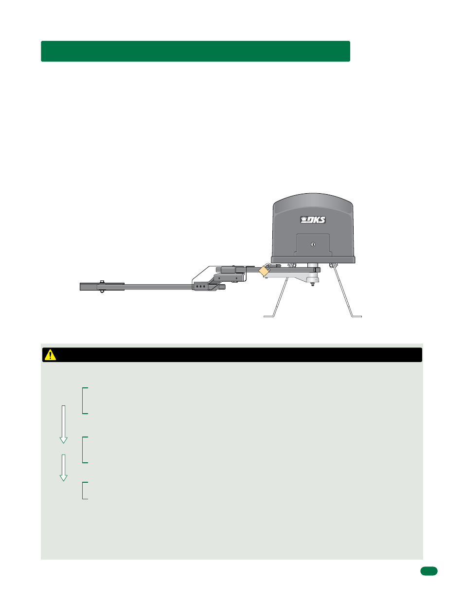
3.4 Automatic Open / Close Limit Adjustment
Crank Arm
Connecting Arm
Flange
Elbow Assembly
Arms in CLOSE Position.
Crank Power Arm
Gate MUST open until it contacts the physical stop “Flange”. (if gate starts to close, turn power off and
change the direction operator opens (SW 2, switch 1). Turn power back on and give open command again).
After the gate cycles to the full OPEN position, the clutch will slip for approximately 2 seconds and shut off.
Auto-close timer will close the gate until it contacts the physical stop “Flange”. (Manual close command
required if timer is turned off). When the gate cycles to the full CLOSE position, the clutch will slip for
approximately 2 seconds and shut off.
Open and close gate positions are now set and will be remembered by the 6300 (until it loses AC power).
Gate will function normally after automatic sequence has finished.
Cycle the operator again. Operator will reach the open and close positions and shut off without the clutch
slipping.
Sequence of Automatic “Gate Cycle” to Set Gate Limits
Open
Close
Sequence
Finished
After the first open command is given to the operator
(gate can be in any position)
:
The 6300’s open/close limits DO NOT have to be physically adjusted. The gate open and close positions are determined by the
physical stop “Flange” on the elbow assembly (See below). The arms MUST already be in the correct closed configuration (See
Section 1.7 on page 14).
DO NOT cycle the operator until the arms are in the correct configuration.
Every time the operator
is powered up, the first open command will automatically run an open and close cycle to locate and remember the gate’s
open and close positions.
Timer:
The Auto-Close Timer should be turned ON (SW 1, switch 4 ON) to allow the operator to run the automatic gate
sequence, otherwise a manual close command will be required to complete this sequence.
Clutch:
The clutch’s factory setting will work correctly for most installations. The clutch must NOT slip while the gate is in
mid-cycle or the gate limits will be incorrect. If the clutch slips during this period, it must be tightened before running this
sequence (See section 3.5 on the next page).
Safety Devices:
Run this sequence before testing any safety features (primary inherent reverse sensor, secondary entrapment
protection, entrapment alarm and reset features).
CAUTION: Keep pedestrians and vehicles clear of the gate while this sequence is running!
Note: If gate encounters an obstruction during this sequencing,
it will automatically continue after obstruction has been cleared.