3 loop detector wiring, Reverse, Reverse shadow automatic exit – Controlled Products Systems Group 6300-080 User Manual
Page 27: Exit loop port reverse loop port, Reverse loops, Shadow loop, Automatic exit loop
6300-065-Z-7-12
25
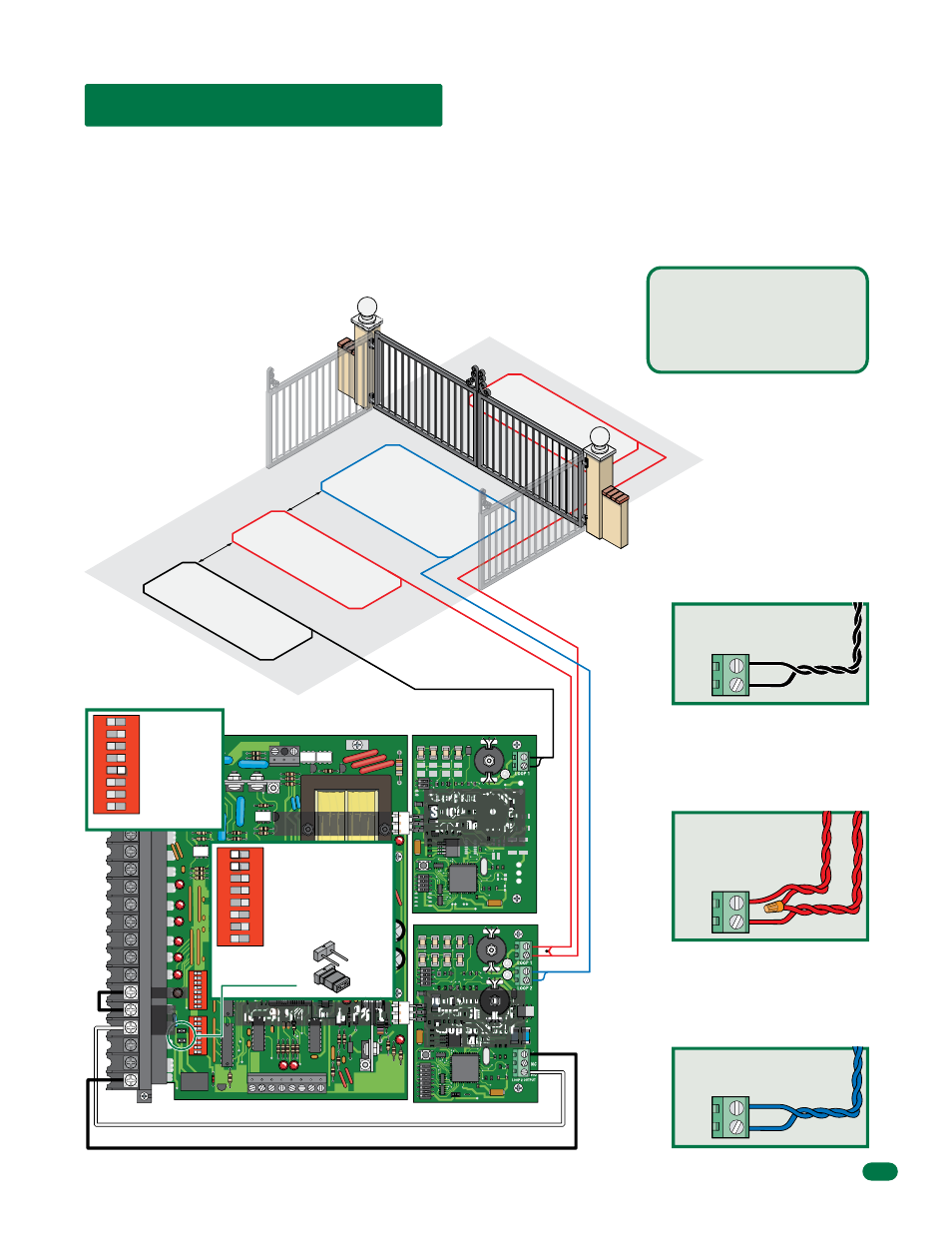
Reverse
4 Ft. min. to avoid reverse
loop inter
ference.
4 Ft. min. to avoid gate
movement inter
ference.
Reverse
Shadow
Automatic Exit
20
19
18
17
16
15
14
13
12
11
10
9
8
7
6
5
4
3
2
1
NC
NO
POWER
1
ON
2
3
4
5
6
7
8
1
ON
2
3
4
5
6
7
8
4.3 Loop Detector Wiring
Com
N.O.
Jumper
4502
Automatic exit loop lead in wires
are twisted approx. 6 twists per
foot.
Reverse loop lead in wires
are twisted approx. 6 twists
per foot and are wired in
series.
Shadow loop lead in wires are
twisted approx. 6 twists per foot.
•
Loop detector wiring is shown for DoorKing
plug-in loop detectors. If other loop detectors are
used, refer to the installation instructions supplied
with those detectors for wiring instructions.
•
If other detectors are used, use a separate power
supply to power these detectors.
•
Loop layout shown is for a typical swing gate
application with two-way traffic, or one-way exit
only
traffic.
Shadow Loop
Output
DoorKing offers a free “Loop and
Loop-Detectors Information
Manual” PDF located at
DoorKing’s web site for more
information. www.dkaccess.com
Exit Loop Port
Reverse Loop Port
LOOP 1
LOOP 2
LOOP 1
To help protect the operator from accidentally closing on vehicles
in the gate’s path, DoorKing highly recommends that loops and
loop detectors be installed. Loops are laid underneath, cut into
asphalt or concrete driveways or buried beneath gravel and earth
driveways. A loop detection system will sense a vehicle like a
metal detector and send a signal to the gate operator preventing
the gate from automatically opening or closing on a vehicle
when it is in the gate’s path. DoorKing recommends that a
licensed installer perform this work.
Shadow
Reverse Loops
are placed on
each side of the gate to prevent the gate
from closing on a vehicle in the gate’s
path. They will stop or reverse the
cycling of the gate while a vehicle is in
or near the gate’s pathway.
Shadow Loop
will ONLY HOLD
the main gates in the Full Open
Position when a vehicle is on the
shadow loop. However, it WILL NOT
stop or reverse the main gates once
they start to close.
SW 2
SW 1
Automatic Exit Loop
Automatically opens the gate for exiting
vehicles without having to use a
transmitter or keypad. The exit loop
can be placed a minimum of 4 feet
away from the reverse loop or far
enough away from the gate so the gate
has started opening or even completely
opened by the time you drive up to it
(Free exit).
Relay Note:
SW 1, switches 1 and 2
Must be OFF.
Shadow Loop Note:
Circuit board relay MUST
be used and set to N.O.
SW 1
1
ON
2
3
4
5
6
7
8
NO
NC
SW 2
1
ON
2
3
4
5
6
7
8
Jumper Note:
SW 2, switch 5
Must be ON.
Relay
Relay
DoorKing Plug-In
Single Channel
Loop Detector
9410
DoorKing Plug-In
Dual Channel
Loop Detector
9409