Controlled Products Systems Group 1602-090 User Manual
Page 32
1601-065-L-3-13
30
REVERSE
SENSITIVITY
TIME
DELAY
POWER
1
ON
2
3
4
5
6
7
8
1
ON
2
3
4
5
6
7
8
NC NO
UP
LOOP
DOWN
LOOP
1 2 3 4 5 6 7 8
9
10 11 12 13
14
1601
SW 1
SW 2
Com
N.O.
CLASS
CE
RT
IFIED TO
CA
N/
CSA
C22.2 NO. 247
CONF
ORMS TO
ANSI/UL-32
5
VEHI
CUL
AR G
ATE
OP
ER
ATOR
HP
533
82
MODE
L
SERI
AL
VOL
TS
PHASE
AM
PS
60
Hz
MA
X GA
TE LOAD
Doo
rKi
ng,
In
c., In
gle
wo
od
, C
A
Mounting Channel
Reversing Edge
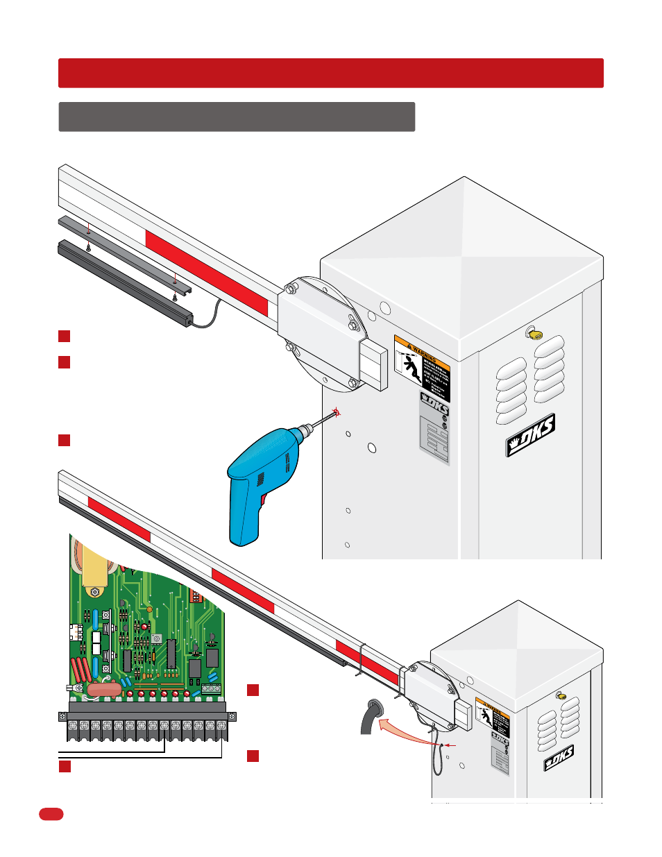
Turn operator power OFF.
Position the mounting channel at the end of
the barrier arm and secure to the bottom of
the arm using 3/4-inch wood screws (not
supplied). Slide the reversing edge into the
mounting channel.
Drill a 1/4-inch hole on the side of the
operator housing beneath the
operator arm shaft.
7.1 Contact Sensor (Reversing Edge)
SECTION 7 - OPTIONAL ACCESSORIES INSTALLATION
In addition to the electronic reversing device (ERD) an optional electric reversing edge may be installed offering additional
protection to the arm, operator and obstruction. Available from DoorKing to fit all arm lengths.
Connect wires to terminals 9 and
14 without interfering with any of
the operator’s moving parts.
CLA
SS
CE
RT
IFIE
D
TO
CAN
/C
SA
C2
2.2
NO.
24
7
CO
NF
OR
MS
TO
AN
SI
/UL
-32
5
VEH
ICU
LA
R GA
TE
OP
ER
AT
OR
HP
533
82
MO
DE
L
SER
IAL
VO
LTS
PHA
SE
AM
PS
60 H
z
MAX
GAT
E L
OA
D
Do
or
Kin
g, In
c., I
nglew
ood,
CA
Wire Loop
Plastic
Grommet
Reversing Edge Assembly
Wire
Tie
Wire
Ties
1
2
3
4
5
6
Secure the wire to the arm and hub
using wire ties (not supplied). leave
a wire loop to allow the arm to
rotate freely.
Install a plastic grommet
(Not supplied) in the
hole to protect the wire
from chaffing on sharp
metal edges.