5 control wiring for single/primary operator – Controlled Products Systems Group 1602-090 User Manual
Page 14
1601-065-L-3-13
12
1. Com
Com
3. 24 Volt
2. Relay
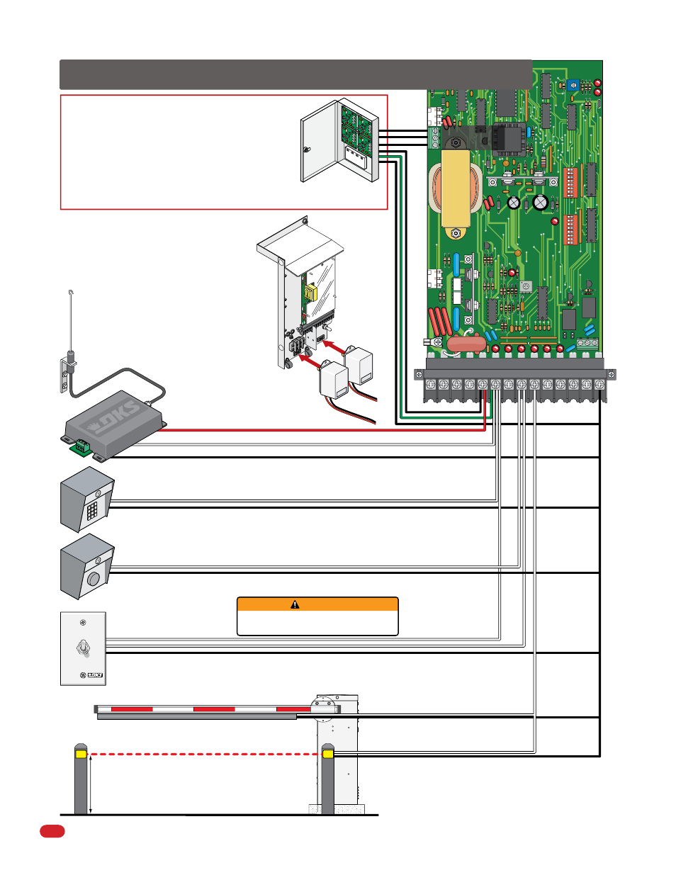
DoorKing Access Control System (Model 1833, 1835, 1837 or
1838) tracker system can be connected.
This system can keep track of gate operator cycle count, shorted
inputs, loop detector problems, any forced entry attempts, if the
gate has struck anything during the open or close cycle, power
interruptions, etc.
For more detailed information refer to the Tracker Installation and
Wiring Manual, DoorKing P/N 2351-010.
Contact Sensor (Reversing Edge)
See page 30
3-Wire Radio Receiver
Up-Inputs
Down-Inputs
Non-Contact Sensor (Photo Sensors)
REVERSE
SENSITIVITY
TIME
DELAY
POWER
1
ON
2
3
4
5
6
7
8
1
ON
2
3
4
5
6
7
8
NC NO
UP
LOOP
DOWN
LOOP
1 2 3 4
5 6
7
8 9
10 11 12 13
14
1601
Terminal 6 required only if the tracker board will activate the gate
operator. Refer to the manual 2351-065 for detailed information.
Manual Gate Control Toggle
P/N 1200-017
Up toggle position: User toggles switch up to hold gate open.
Center toggle position: Is neutral for normal operation.
Down toggle position: User momentarily toggles switch down to open gate.
User MUST make sure gate area IS CLEAR
before manually operating gate arm.
21” Typical Beam Height.
27.5” Max. Beam Height.
2.5 Control Wiring for Single/Primary Operator
OPEN
HOLD OPEN
WARNING
Contact and Non-Contact Sensors Note:
Helps minimizes the potential of the arm
lowering on vehicular or other traffic that
loops cannot sense.
Gate Operator
Data Terminal
Coax Antenna Kit
P/N 1514-073
Antenna mounted
outside operator
housing.
Gate
Tracker
(Quad Box
Shown)
REV
ER
SE
SE
NS
ITIVITY
TIM
E
DELA
Y
PO
WE
R
1
ON
2
3
4
5
6
7
8
1
ON
2
3
4
5
6
7
8
NC
NO
UP
LOO
P
DOW
N
LOOP
Electronic
Box Assembly
115 VAC
Convenience
Outlets
Power safety and
opening devices
that require 115
VAC power.