Alarms, Alarms -52 – CONTREX MLP-Trim User Manual
Page 92
3 - 52
Alarms
The Control Parameters for Alarms are identical for both the Master and the Follower
modes of operations. By entering values in the Control Parameters for the Alarms
(CP-12, CP-13, CP-14, CP-15), you can establish circumstances under which the
MLP–Trim will alert you to potential operating problems. The Alarm 1 Format (CP-10)
and Alarm 2 Format (CP-11) can be set to activate at any combination of low speed,
high speed, ramped error or scaled error conditions. Alarm 1 Format is used to control
Dig_Out1 (J6 pins 15, 17). Alarm 2 Format is used to control Dig_Out2 (J6 pins 16, 17).
The alarm outputs can be wired to activate a warning light, a warning sound, or to shut
down the system under specified conditions.
The MLP–Trim comes factory pre-loaded with default Control Parameters for Alarms.
These default parameter values are set for widely generic conditions that generally will
not activate the alarm. This allows you to either operate your system unfettered by the
alarm or design your own alarm conditions that are unique to your system. The factory
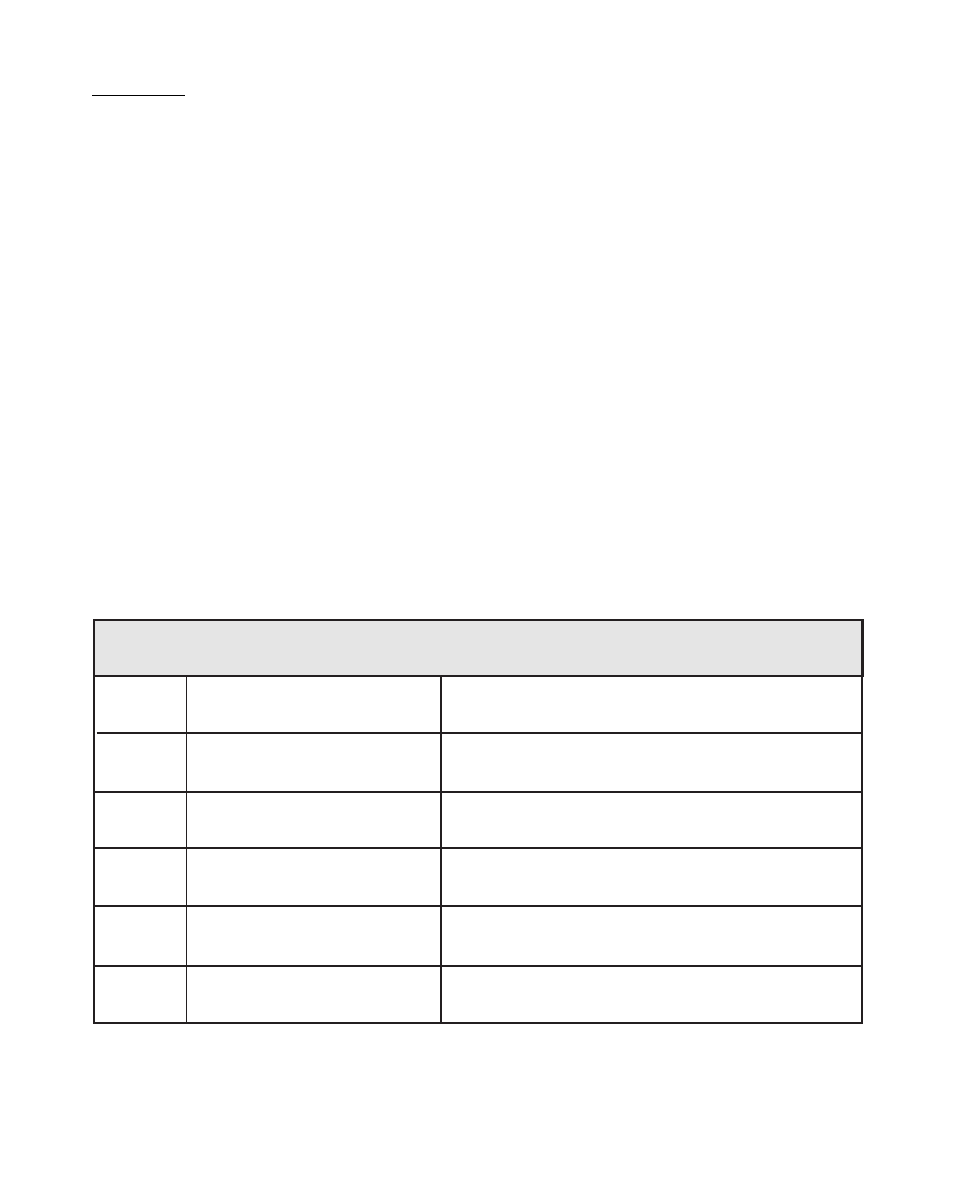
default Control Parameters for the Alarms are found in Table 3-43. To modify these
default parameters, refer to Table 3-44.
Table 3-43 Default Alarms Control Parameters
CP
Parameter Name
Parameter Value
CP-10
Alarm 1 Format
15
CP-11
Alarm 2 Format
15
CP-12
Low Alarm
0
CP-13
High Alarm
2000
CP-14
Ramped Error Alarm
2000
CP-15
Scaled Error Alarm
2000