Performance monitoring, Performance monitoring -68 – CONTREX MLP-Trim User Manual
Page 108
3 - 68
Performance Monitoring
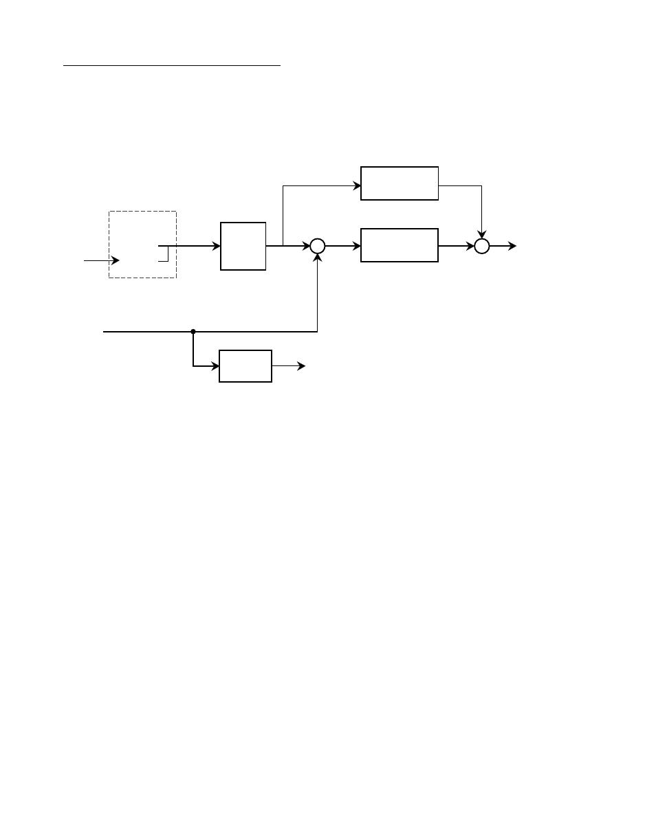
Performance Monitor Parameters monitor the performance of the MLP–Trim and your
system. Figure 3-2 is a block diagram of the internal control structure of the MLP–Trim
and the Performance Monitor Parameters.
Lead
Frequency
(MP-41)
Feedback
Frequency
(MP-43)
Active
Scaling
(MP-50)
Master
Follower
Feedback
Scaling
Tach
(MP-40)
Scaled
Reference
(MP-45)
Accel /
Decel
Ramped
Reference
(MP-46)
Deviation
(MP-44)
Trim
Output
(MP-48)
Speed Command
Out (MP-47)
Feedforward
PID Compensation
Routine
+
+
–
+
+
+
Figure 3-2 MLP–Trim Internal Structure
MP-40 TACH
Tach (MP-40) is the feedback displayed in scaled Engineering Units or RPM. In the
Master mode, Tach (MP-40) will display the feedback in Master Engineering Units
(CP-20). In the Follower mode, Tach (MP-40) will display either the E.U.s/Time or the
feedback to Lead ratio in Follower Engineering Units (CP-21), depending on the value
in Display Mode Follower (CP-64). In Jog or the Direct mode, Tach (MP-40) will display
the feedback in RPMs. The feedback is read by the MLP–Trim every ten milliseconds.
The readings are summed, then averaged for one second before the Tach is displayed.
MP-42 PULSE ERROR COUNT
The Pulse Error Count indicates the difference between the Lead and Feedback pulses
received during the Follower mode of operation. It is an indicator of the position error
between the lead and follower devices. This error is cleared to zero when the MLP-Trim
enters the stop state.