Ken Tool Bendix ADB22X-V Air Disc Brakes User Manual
Page 26
26
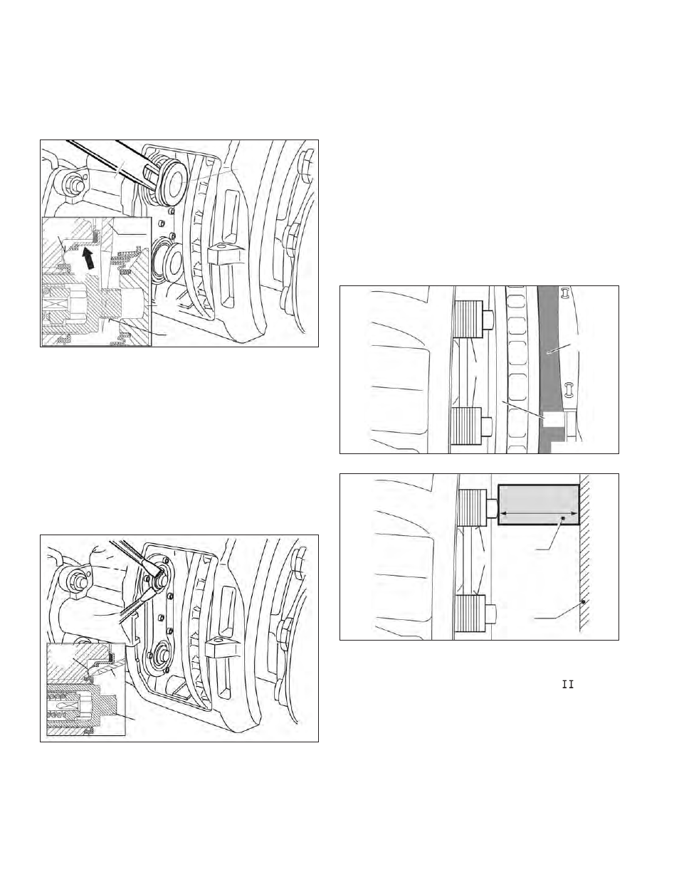
Figure 47 inset) should be used to move the boot
and allow the wedge fork (“A” in Figure 48) to be
inserted. CAUTION: Do not insert the screw driver
more than ¼ inch. Take care not to damage the
inner sealing face (see arrow “X” in Figure 49).
Gouges or grooves will prevent a good seal and
will require that the caliper be replaced.
13
T15
22
A
13
161
X
FIGURE 48 - WEDGE TOOL USE
5.5.6 The tappet and boot assemblies (13) can then be
removed from the threaded tubes (16) by using the
wedge fork (T15). Be sure to orient the wedge tool
with the tapered side towards the tappet.
5.5.7 Remove the old tappet bushings (161).
5.5.10 See Figure 49. Carefully remove the inner seal
using one or two fl at-blade screwdrivers as shown.
Caution: Do not insert the screwdrivers so far that
they come into contact with the threaded tubes.
Damage to the threaded tubes would require that
the brake be replaced.
A
22
16
FIGURE 49 - INNER SEAL REMOVAL
5.5.8 Inspect the inner sealing face for damage. If
damage is found that would cause the inner seals
not to be able to seal properly, the caliper/carrier
assembly must be replaced. Clean the area around
the inner seal.
5.5.9 Inspect the threaded tubes (16). See Figures 50
and 51. Extend the tubes, but by less than 1.75 in.
(44.5 mm), by turning the shear adapter (61)
clockwise. Inspect the threads for rust, corrosion, or
damage etc. If there is evidence of damage to the
threads; signifi cant rust; or corrosion, the caliper/
carrier assembly must be replaced.
If the technician is working with the caliper on the
vehicle, the technician may place a new brake pad
(12) into the outboard gap to help avoid the loss
of thread engagement of the threaded tubes. See
Figure 51.
If the work is being carried out at a workbench, the
technician may insert a 2.76 in. (70 mm) spacer
(See callout “E” in Figure 52) into the caliper (1) to
help avoid the loss of thread engagement.
12
16
46
FIGURE 50 - USE OF A NEW BRAKE PAD AS A SPACER
E
16
1
2.76 in.
(70 mm)
FIGURE 51 - USE OF A SPACER (OFF-VEHICLE INSPECTION)
5.5.11 For threads that are in good condition, grease the
threads with white grease (Part No.
14525 or
K021964). Before installing the replacement inner
seals (22), retract the threaded tubes by turning the
shear adapter (61) counter-clockwise.
Note: If the shear adapter fails while you are retracting
the threaded tubes, you may try again with another
(new) shear adapter. If this also fails, this indicates
that the adjuster mechanism is damaged and the
caliper must be replaced.