Ken Tool Bendix ADB22X-V Air Disc Brakes User Manual
Page 21
21
1. Check for uneven wear from one end of each pad
to the other. If the difference in wear is greater
than 0.080 in. (2 mm.), service the guide pins
(See Section 5.6).
2. Compare the thickness of the inboard and
outboard pads of each set. If the difference
between them is greater than 0.119 in. (3 mm.),
this also would show that the guide pins are
ready to be serviced.
5.2.12 Inspect the Brake Rotor (See Section 4.4).
5.2.13 Inspect the guide pins (See Sections 2.2 & 4.1).
Important: To maintain optimal braking, Bendix
strongly recommends that whenever brake pads
are replaced, the complete axle set be replaced
together. Use only pads which are permitted by the
vehicle manufacturer, axle manufacturer, and/or disc
brake manufacturer. Failure to comply with this may
invalidate the vehicle manufacturer’s warranty.
Before installing the brake pads, use the adjuster to
fully retract the tappets to provide adequate clearance.
5.2.15 Clean the surfaces that will come in contact with
the brake pad.
Caution: When installing pads and retaining springs,
where appropriate, use heavy duty gloves and always
keep fi ngers away from potential pinch hazard areas.
12
2
FIGURE 39 - PAD RETAINING SPRING INSTALLATION
5.2.16 Install the pad retaining springs(2) onto the brake
pads(12) by inserting one end of the spring onto
the lug at the top of the brake pad (See Figure 41).
Carefully apply enough force to permit the second
lug to fully engage, taking care to keep fi ngers etc.
away from the spring as it seats.
5.2.17 Pull the caliper fully outward and install the outboard
pad. Move the caliper fully inward and install the
inboard pad.
5.2.18 To reinstall wear indicators (if used): Insert the
wear sensors into position in the new brake
pads. Route the sensor cable through the cable
protection plate channel and secure the plate with
the mounting hardware retained at disassembly.
(See Section 5.2.)
CAUTION: Never turn the adjuster (23) without the
shear adapter (61) installed. The shear adapter is a
safety feature and is designed to prevent too much
torque being applied. The shear adapter will fail (by
breaking) if too much torque is used.
Note: Always double-check that the spring brake is
released (where applicable) if a shear adapter fails; if this
step was missed, the shear adapter will break off, and it
may incorrectly that the caliper is seized.
If the shear adapter fails, you may attempt a second time
with a new (unused) shear adapter. In cases where a
second failure of the shear adapter confi rms that the
adjustment mechanism is seized, the caliper must be
replaced.
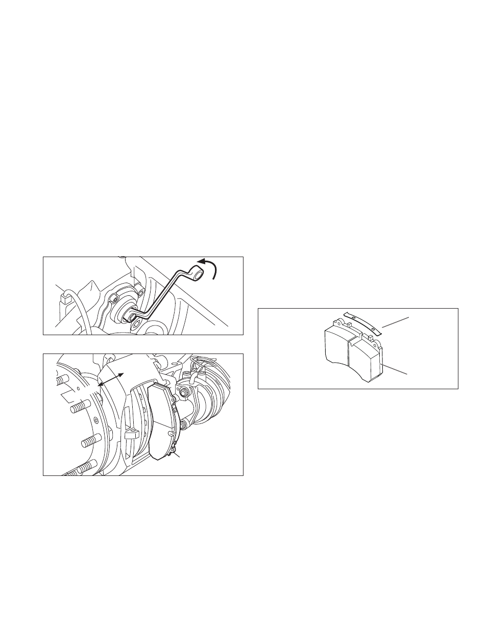
5.2.8 Use a 10 mm. six-point box wrench (See Figure 37)
to turn the adjuster counterclockwise until suffi cient
space exists to remove the brake pads. A clicking
noise occurs each time the adjuster turns.
CAUTION! Avoid overloading or damaging the adjuster
shaft. Do not use an open-ended wrench since it may
damage the adjuster shaft.
FIGURE 37 - BACKING OFF THE ADJUSTER FOR PAD REMOVAL
Inboard Pad
Ou
tbo
ard
Inboard
FIGURE 38 - PAD REMOVAL
5.2.9 See Figure 38. Move the caliper fully inward and
remove the inboard pad, then move the caliper fully
outward and remove the outboard pad.
5.2.10 Repeat the pad removal procedure for the other
end of the axle.
5.2.11 To confi rm that the guide pins are sliding freely,
examine the pads just removed for uneven wear.
Use these two inspections: