2 pad replacement – Ken Tool Bendix ADB22X-V Air Disc Brakes User Manual
Page 20
20
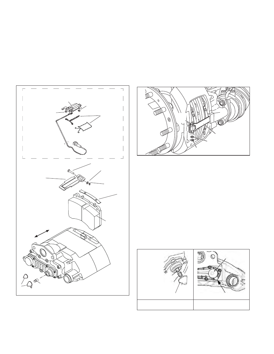
and retain the mounting hardware for the cable
protection plate. The cable protection plate can
then be set aside while servicing the pads. Note the
position of the sensors in the brake pad channels,
and carefully remove them. In most cases you do
not need to release the cable connector in order to
move the sensors away from the pad installation
work area. Inspect the wear sensors - replace if
damaged or abraded.
5.2.4 See Figure 36. Remove and discard the pin
retention clip (26) and washer (5).
44
Pin
26 Spring Clip
45 Washer
11 Pad Retainer Bar
FIGURE 34 - PAD RETAINER BAR REMOVAL
5.2.5 While pressing against the pad hold down bar,
remove the pad retainer bar pin (11). Discard the
hold down bar.
5.2.6 With the spring brake released (or caged), remove
the adjuster cap (37) using the tab, taking care not
to move the shear adapter (61). Note: One of two
styles of adjuster cap (stamped metal or plastic
adjuster cap) may be found; use the same style as
a replacement in step 5.2.21.
5.2.7 Inspect the sheer adapter (61). If significant
corrosion and/or damage is present, remove the
adjuster adapter using needle-nose pliers and
replace with the adapter supplied in the kit and
clean as necessary.
61 Adapter
23 Adjuster
37
Cap
Tab
Tab
37
Cap
FIGURE 35 - EXPLODED VIEW
OF ADJUSTER AND ADAPTER
FIGURE 36 - CAP INSTALLED:
TAB LOCATION
For illustration purposes, the exploded view (Figure 36)
shows the adjuster (23) and shear adapter (61) separated.
When using the adjuster mechanism, always have the
shear adapter installed on the adjuster.
5.2 PAD REPLACEMENT
5.2.1 CAUTION: Follow all safe maintenance
practices, including those listed on page two of
this document. Park the vehicle (by other means
than the foundation brakes) on level ground and
chock the wheels.
The Bendix DVD (BW7356) shows this procedure.
Important: If the vehicle is equipped with spring brakes,
cage the spring brakes on all axles to be worked on.
Consult the vehicle manufacturer’s instructions as
necessary.
Ou
tbo
ard
Inboard
12
2
11
44
45
26
61
37
ELECTRONIC WEAR
SENSOR
(if installed)
103
Cable to Electrical
Supply
104
Cable Protection
Plate
101
Sensor
101
Sensor
105
Cable Guide
(2 alternate
designs used)
FIGURE 33 - PAD REPLACEMENT
5.2.2 Raise the complete axle to be worked on until the
tires clear the ground. See the vehicle maintenance
manual instructions for removing the wheels.
5.2.3 If the air disc brake is equipped with an electronic
wear sensor indicator (see top of Figure 35), remove