Ken Tool Bendix ADB22X-V Air Disc Brakes User Manual
Page 24
24
5.4
SPRING OR SERVICE BRAKE
5.4.1 CAUTION: Follow all safe maintenance
practices, including those listed on page two of
this document. Park the vehicle (by other means
than the foundation brakes) on level ground and
chock the wheels.
5.4.2 Use the spring brake manufacturer’s recom-
mended safety practices in all cases.
Some spring brake and vehicle manufacturers
permit caging the spring brake while the spring
brake is engaged.
THE FOLLOWING INSTRUCTIONS ARE FOR BENDIX
®
BRAND ACTUATORS.
5.4.3 With the vehicle on a level surface and the wheels
properly chocked, apply air to release the spring
brakes (parking brakes) by using the dash-mounted
air control valve. Back out the release bolt (Figure
43, arrow “D”), using a maximum torque of 26 ft. lbs.
(35 N·m) to cage the air released spring force on
the push rod.
D
A
A
18/1
B
B
FIGURE 43 - ACTUATOR SPRING CAGING AND REMOVAL
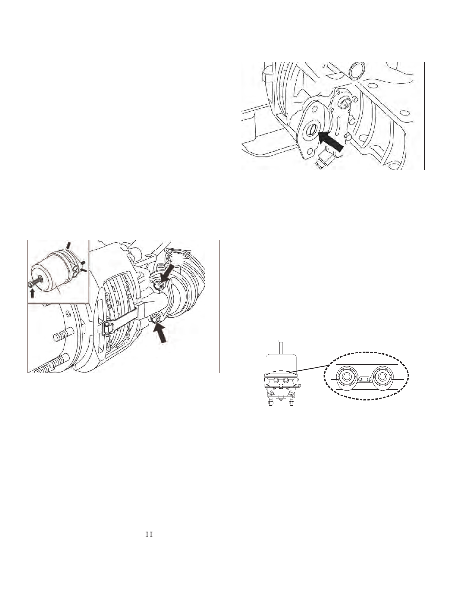
5.4.4 Exhaust the air from the brake chambers by using
the dash-mounted air control valve. With all air
pressure drained from the system, disconnect the
air hoses from the brake chamber. While supporting
the brake chamber in position, remove and discard
the brake chamber mounting nuts (Figure 45,
arrows marked “B”). Remove the brake chamber.
Note: Before removing the brake pads it is strongly
recommended that the air disc brake adjuster mechanism
be checked for correct operation (See Section 4.2).
5.4.5 Re-installation. Before installing the brake chamber,
the actuator fl ange (See Figure 46, arrow “C”) must be
cleaned and inspected. Consult the vehicle manual.
The spherical cup in the lever (19) must be greased
with white grease (Part No. 14525 or K021964).
Add grease to the rubber gasket on the chamber.
CAUTION: Do not use grease containing molybdenum
disulfate.
5.4.6
The seal, as well as the push rod area, must be
clean and dry.
C
FIGURE 44 - SPRING BRAKE INSTALLATION
CAUTION: Do not use brake chambers with seals that
have a thickness less than 0.12 in. (3 mm). Use only
actuators which are recommended by the vehicle
manufacturer.
5.4.7 Install the brake chamber using new self-locking
nuts (EN ISO 10513). Alternately tighten both the
nuts step by step up to a fi nal torque of 133 ± 7 ft. lbs
(180 ± 10 N·m). Bendix strongly recommends
that new nuts be used.
5.4.8 Re-connect the air hose(s) and be sure that each
hose is not twisted or in contact with moving vehicle
components. The air hose routing must allow for full
caliper travel. Note that for spring brake service
chambers the ports are indicated by: “11” Service
Brake Port and “12” Spring Brake Port
FIGURE 45 - PORT DESIGNATIONS
Note: Where a new spring brake chamber is being
installed, note that typically drain plugs are installed (See
Figure 43, arrows marked “A”). After installation, remove
whichever plug is at the lowest position. Be sure that all
other drain holes remain plugged. The selected drain hole
must be aligned downwards (or within ±30°) when installed
on the vehicle. In the case of spring brake chambers, install
the pads before uncaging the spring.
5.4.9 Before returning vehicle to service, with the system
pressurized, using a soap solution, check for air
leakage. Minimal leakage in the area around the push
rod hole is permitted (100 SCCM), and a one-inch
bubble in one minute at the hose fi tting is acceptable.
If abnormal leakage is detected, the diaphragm must
be replaced, or fi tting adjusted, respectively.