3 caliper/carrier/actuator assembly – Ken Tool Bendix ADB22X-V Air Disc Brakes User Manual
Page 22
22
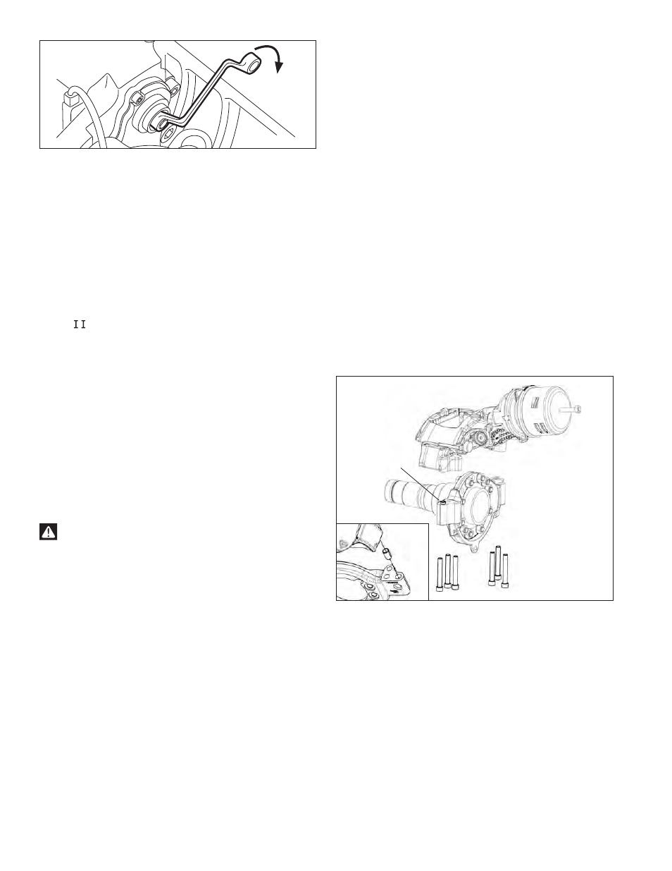
FIGURE 40 - RUNNING CLEARANCE ADJUSTMENT
5.2.19 Move the caliper to the full outboard position.
5.2.20 Using a 10 mm. six-point box wrench, turn the Shear
Adapter (61) counter-clockwise and listen for
the sound of 3 clicks as the mechanism backs-off
(increases) the running clearance. Note: Do not
use an open-ended wrench as this may damage
the adapter. (See Figure 40).
5.2.21 Select the correct replacement adjuster cap from
those supplied with the kit. Lightly grease adjuster
cap with Renolit HLT2 white grease (part number
14525) and install the cap.
5.2.22 Push the new pad retainer bar (11) into the groove
of the caliper. Press down on the pad retainer bar,
and insert the pad retainer pin (44), with the pin
pointing downwards, where possible. Install the
supplied washer (45) and then the spring clip (26).
5.2.23 Apply and release the brakes. The hub should
turn easily by hand after applying and releasing the
brake.
5.2.24 Re-check the running clearance. Readjust if
necessary.
5.2.25 Reinstall the wheel, following the vehicle manual
instructions.
WARNING!
The brake pads and rotor must be maintained within
the recommended wear limits. Failure to monitor wear
and replace the brake pads and rotor when required
may result in diminished brake performance.
5.3 CALIPER/CARRIER/ACTUATOR
ASSEMBLY
5.3.1 CAUTION: Follow all safe maintenance
practices, including those listed on page two of
this document. Park the vehicle (by other means
than the foundation brakes) on level ground and
chock the wheels.
The brake pads must be removed (See Section
5.2.0) and actuator disconnected (and caged if
a spring brake), see Section 5.4.0.
CAUTION: When using a hoist to support the
air disc brake, do not attempt to use the pad
retainer bar as a bracing point. It is not designed
to support the weight of the brake. Use instead
a brace (or chain) wrapped around the entire
brake to attach the hoist.
5.3.2 In all cases check that the current hose routing
arrangement does not restrict the full travel of the
caliper before beginning work on the assembly.
5.3.3 Disconnect the air hose(s) from the service or spring
brake chamber.
Vertical Mounting Bolt Style
Mounting Bolts
(6 total - washers
not required)
Anchor Plate/
Torque Plate
Caliper/Carrier Assembly (Showing
Spring Brake Actuator )
Alignment
Bushing
Alignment
Bushing
FIGURE 41 - VERTICAL MOUNT CALIPER/CARRIER
5.3.3 See Figure 41. Supporting the air disc brake by
necessary means, remove the six (6) mounting
bolts/washers and discard. Note: Bendix strongly
recommends that during re-assembly these bolts
are replaced - see your vehicle manufacturer for
replacement hardware. Lift the caliper up off the
anchor plate.
The vertical bolt assembly includes an alignment bushing.
This bushing must be saved for re-use during re-
assembly of the brake. The bushing mounts in the torque
plate and maintains the correct alignment of the brake
assembly relative to the rotor.