Wiring diagram, Supply and end connections of the ct transmitter – Fluid Components International CMU User Manual
Page 46
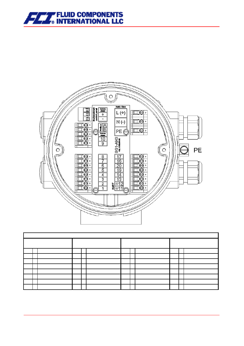
11.5.2 Wiring
diagram
11.5.2.1 Wiring diagram for the integral mount configuration of sensor and CT
Supply and end connections
of the CT transmitter
17 + Binary output 1
47 + Binary output 1
17 + Binary output 1
17 + Binary output 1
16 -
(pulse/frequency)
46 -
(pulse/frequency)
16 -
(pulse/frequency)
16 -
(pulse/frequency)
20 + Binary output 2
50 + Binary output 2
20 + Binary output 2
20 + Binary output 2
19 -
(status output)
49 -
(pulse/frequency)
19 -
(pulse/frequency)
19 -
(pulse/frequency)
14 + Current output 2
44 + Current output 2
34 + Binary output 3
36 B RS485
13 -
(0/4-20 mA)
43 -
(0/4-20 mA)
33 -
(status output)
35 A
(Modbus)
12 + Current output 1
42 + Current output 1
12 + Current output 1
12 + Current output 1
11 -
(0/4-20 mA HART®)
41 -
(0/4-20 mA HART®)
11 -
(0/4-20 mA HART®)
11 -
(0/4-20 mA)
Modbus (planned)
(RS485 - IS)
Process outputs wiring
Standard EEx ia /
Not Ex
Standard EEx e
Custody transfer
Note: RS 485 not currently available
Page 46 of 112
CMU & CT OPERATING MANUAL
- FC88 KIT (5 pages)
- Quality Assurance Manual (94 pages)
- 8-66B_12-64B Series Manual Installation (4 pages)
- 8-66B_12-64B Series Manual Operation (2 pages)
- 8-66B_12-64B Series Manual Maintenance (2 pages)
- 8-66B_12-64B Series Manual Troubleshooting (4 pages)
- 8-66B_12-64B Series Manual Guide (4 pages)
- 8-66B_12-64B Series Manual Cover Page (10 pages)
- 8-66B_12-64B Series Manual General Information (2 pages)
- 8-66B_12-64B Series Manual Drawings (2 pages)
- 8-66B_12-64B Series Manual Glossary (2 pages)
- 8-66B_12-64B Series Manual CE Conformance (2 pages)
- FLT Series (65 pages)
- FLT93 (12 pages)
- FLT Series Rack Mount (61 pages)
- FLT93 Nuclear (58 pages)
- FR73B Manual Installation (2 pages)
- FR73B Manual Operation (2 pages)
- FR73B Manual Maintenance (2 pages)
- FR73B Manual Troubleshooting (4 pages)
- FR73B Manual Cover Page (10 pages)
- FR73B Manual General Information (2 pages)
- FR73B Manual Drawings (2 pages)
- FR73B Manual Glossary (2 pages)
- FR73B Manual Customer Service (4 pages)
- FR73B Complete Manual (20 pages)
- FS10 Button Setup Quick Guide (4 pages)
- FS10 Field Quick Setup Mode (1 page)
- FS10A (54 pages)
- LS2000 (12 pages)
- OEM MASS FLOW SWITCH (2 pages)
- RF83 Manual Customer Service (4 pages)
- RF83 Manual Glossary (2 pages)
- RF83 Manual Drawings (10 pages)
- RF83 Manual General Information (2 pages)
- RF83 Manual Cover Page (10 pages)
- RF83 Manual Installation (4 pages)
- RF83 Manual Operation (4 pages)
- RF83 Manual Maintenance (2 pages)
- RF83 Manual Troubleshooting (6 pages)
- CMB (106 pages)
- CMF Series Manual Installation of Flow Element (9 pages)
- CMF Series Manual Installation of Electronics (14 pages)
- CMF Series Manual Table of Contents (3 pages)
- CMF Series Manual Technical Data (10 pages)