The cmu sensor, Application domain of the cmu sensor, Mode of operation – Fluid Components International CMU User Manual
Page 14: Measuring principle, System configuration, Input, Custody transfer operations
3. The CMU sensor
3.1
Application domain of the CMU sensor
The CMU sensor is intended for use solely for direct and continuous mass flow measurement of liquids
and gases, irrespective of their conductivity, density, temperature, pressure, or viscosity. The sensor is
also intended for use for the direct and continuous mass flow measurement of chemical fluids, suspen-
sions, molasses, paint, varnish, lacquer, pastes and similar materials.
[
]
v
m
F
C
×
⋅
⋅
=
ω
2
3.2
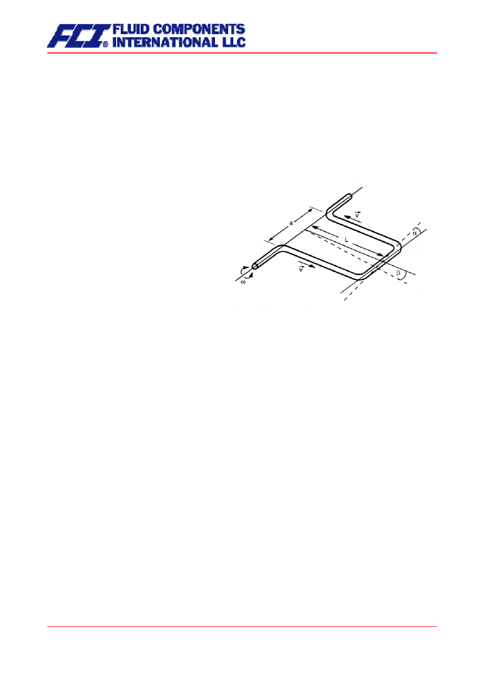
Mode of operation
3.2.1 Measuring
principle
The Coriolis mass flowmeter is based on the
principle whereby in a rotating system a force
(known as the Coriolis force) is exerted on a
mass at a rotation point that is moving towards
or away from this point.
3.2.2 System
configuration
The flowmeter consists of a sensor that is mounted in a pipe, and a transmitter (see Section 5
Application domain of the CT
on pp. 35), that can be directly mounted on the sensor or installed sepa-
rately (e.g. on a wall).
The transmitter oscillates the flow tubes in the sensor over a excitation coil and picks up, via the sensor
coil, the measuring signal which is proportional to the mass flow. After being temperature compensated,
the measuring signal is converted into an analog output signal that is consistent with the measuring range
setting.
3.2.3 Input
Measured variables: mass flow, density, temperature; volume flow is calculated
3.3
Custody transfer operations
Units designated for custody transfer operation may be certified in accordance to the local or national
ordinance. Transmitters ordered for custody transfer applications incorporate special tamper-proof soft-
ware, sealed and certified, that prevents the reset of the internal totalizer.
Page 14 of 112
CMU & CT OPERATING MANUAL