Configuration of the pcb devicenet, 7 terminating circuit for devicenet systems – Burkert Type 8691 User Manual
Page 46
46
DeviceNet
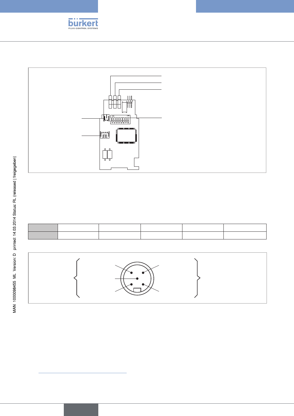
11.6.2 configuration of the pcB Devicenet
Valve connection
Internal connection
LED – pilot valve (yellow)
Device status LED (two-colored: red/green)
Bus LED (two-colored: red/green)
DIP switches for
bus address and baudrate
Figure 38:
DeviceNet PCB
11.6.3 Bus connection (circular connector m12 x 1, 5-pole, male)
The control head features a 5-pole micro-style circular connector.
The following configuration conforms to the DeviceNet specification.
pin
1
2
3
4
5
signal
Shielding
V +
V –
CAN_H
CAN_L
Table 14:
Pin assignment circular plug-in connector DeviceNet
Pin 4: CAN_H
white
Pin 5: CAN_L
blue
Pin 1: Drain
(Shield)
Pin 3: V–
black
Pin 2: V+
red
Data lines
Supply voltage
11 ... 25 V DC
max. power 3 W,
if valve is switched
Figure 39:
View of plug from the front onto the pins, the soldered connections are behind
11.7 Terminating circuit for Devicenet systems
When installing a DeviceNet system, ensure that the terminating circuit of the data lines is correct.
The circuit prevents the occurrence of interference caused by signals reflected onto the data lines.
The trunk line must be terminated at both ends with resistors of 120 Ω each and 1/4 W power loss
(see “Figure 40: Network topology, DeviceNet”).
english
Type 8691