4 electrical installation as-interface, Safety instructions – Burkert Type 8691 User Manual
Page 36
36
AS-Interfaceinstallation
10.4 electrical installation as-interface
10.4.1 safety instructions
Danger!
rrisk of electric shock.
▶ Before working on equipment or device, switch off the power supply and secure to prevent reactivation.
▶ Observe applicable accident prevention and safety regulations for electrical equipment.
Warning!
risk of injury from improper installation.
▶ Installation may be carried out by authorized technicians only and with the appropriate tools.
risk of injury from unintentional activation of the system and an uncontrolled restart.
▶ Secure system from unintentional activation.
▶ Following installation, ensure a controlled restart.
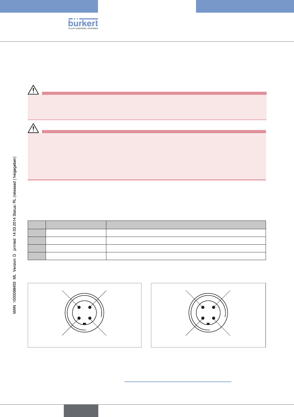
10.4.2 connection with circular plug-in connector m12x1, 4-pole,
male
Bus connection without external / with external supply voltage
pin
Designation
configuration
1
Bus +
AS-Interface bus line +
2
NC or GND (optional)
not used or external supply voltage - (optional)
3
Bus –
AS-Interface bus line -
4
NC or 24 V + (optional)
not used or external supply voltage + (optional)
Table 8:
Pin assignment circular plug-in connector AS-Interface
Views of plug: From the front onto the pins, the soldered connections are behind
Pin 4:
NC
Pin 1:
Bus +
Pin 3:
Bus –
Pin 2:
NC
Pin 4:
24 V +
Pin 1:
Bus +
Pin 3:
Bus –
Pin 2:
GND
Figure 28:
Bus connection without external supply
voltage
Figure 29:
Bus connection with external supply voltage
(optional)
The teach function can now be used to automatically determine and read in the end positions of the valve
(description of the teach function see chapter “10.5 Teach function (calibrating the end position)”).
english
Type 8691