Burkert Type 8691 User Manual
Page 20
20
Installation
7.3
installing the control head Type 8691 on process
valves belonging to series 20xx
Procedure:
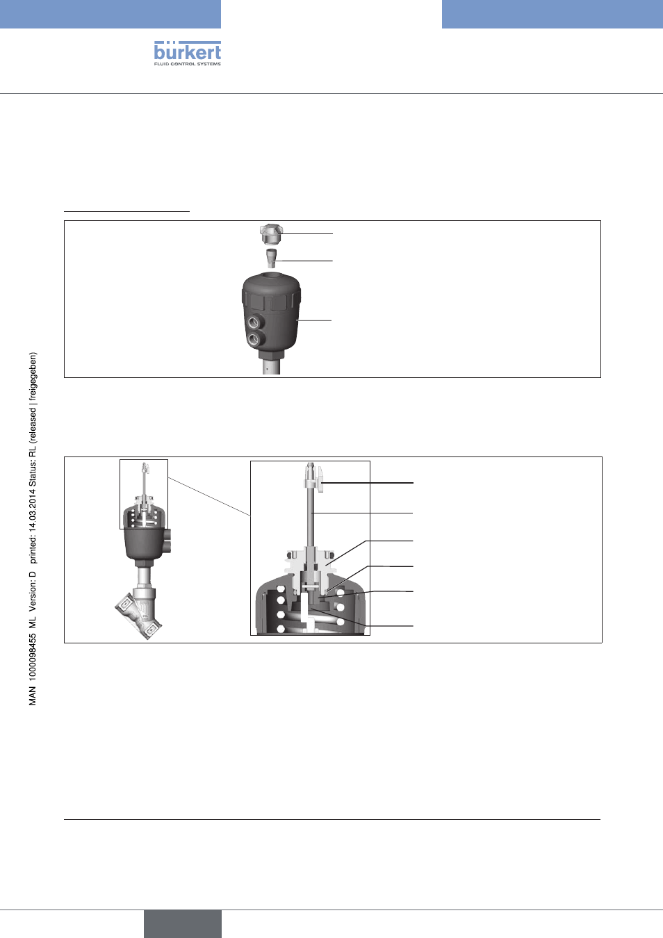
1. install switch spindle
Transparent cap
Position indicator
Actuator
Figure 9:
Installation of the switch spindle (1), series 20xx
→
Unscrew the transparent cap on the actuator.
→
Using a hexagon socket key, unscrew the orange/yellow position indicator from the inside of the actuator.
Guide element
O-ring
Plastic part
(of the switch spindle)
Puck
Switch spindle
Spindle (actuator)
Figure 10:
Installation of the switch spindle
(2), series 20xx
→
Press the O-ring downwards into the cover of the actuator.
→
Manually screw the switch spindle (and the plugged-on guide element) together with the plastic part onto the
spindle of the actuator, but do not tighten spindle yet.
→
Tighten the guide element with a face wrench
1)
into the actuator cover (torque: 8.0 Nm).
→
Tighten the switch spindle on the spindle of the actuator. To do this, there is a slot on the upper side (torque:
1.0 Nm).
→
Push the puck onto the switch spindle until it engages.
1)
journal Ø: 3 mm; journal gap: 23.5 mm
english
Type 8691