Electrical installation 24 v dc, Safety instructions, Electrical installation with cable gland – Burkert Type 8691 User Manual
Page 27: 9electrical installation 24 v dc, 1 safety instructions, 2 electrical installation with cable gland
27
Electricalinstallation24VDC
9
elecTrical insTallaTiOn 24 V Dc
Two kinds of connections are used for the electrical bonding of the control head:
• cable gland
with cable gland M16 x 1.5 and screw terminals
• multi-pole
with circular plug-in connector M12 x 1, 8-pole
9.1
safety instructions
Danger!
risk of electric shock.
▶ Before working on equipment or device, switch off the power supply and secure to prevent reactivation.
▶ Observe applicable accident prevention and safety regulations for electrical equipment.
Warning!
risk of injury from improper installation.
▶ Installation may be carried out by authorized technicians only and with the appropriate tools.
risk of injury from unintentional activation of the system and an uncontrolled restart.
▶ Secure system from unintentional activation.
▶ Following installation, ensure a controlled restart.
9.2
electrical installation with cable gland
noTe!
Breakage of the pneumatic connection pieces due to rotational impact.
▶ When unscrewing and screwing in the body casing, do not hold the actuator of the process valve but the
connection housing.
→
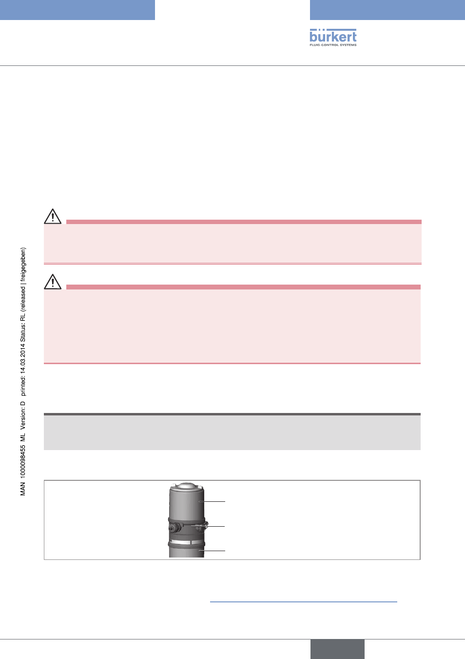
Unscrew the body casing (stainless steel) in a counter-clockwise direction.
Body casing
Connection housing
Actuator
Figure 18:
Open control head
→
Push the cables through the cable gland.
→
english
Type 8691