Burkert Type 8690 User Manual
Page 23
23
Electricalinstallation
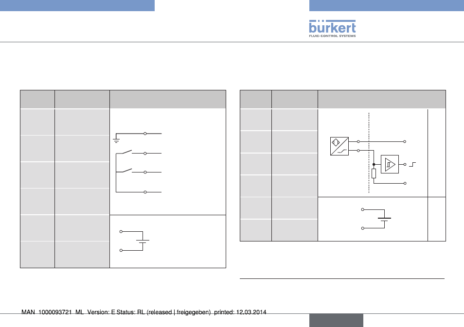
9.2.2 connection diagram
with three-wire proximity switches
(inductive limit switches)
terminal configuration
external circuit
1
INI - (GND)
Supply
2
1
3
4
Output 1 (24 V)
GND
Output 2 (24 V)
+24 V DC
2
INI 1 OUT
Output
3
INI 2 OUT
Output
4
INI + (24 V DC)
Supply
5
Valve control
0 / 24 V DC
5
6
0/24 V DC ±10 %
Residual ripple 10 %
6
Valve control
GND
Tab. 3: Connection diagram with three-wire proximity switches
9.2.3 connection diagram
with two-wire proximity switches
(inductive namur limit switches)
terminal configuration external circuit
1
INI Top +
NAMUR-
Sensor
Explosion
protected area
Non-hazardous
area
+8,2 V DC
0 V
R
1 / 3
2 / 4
3)
2
INI Top -
3
INI Bottom +
4
INI Bottom -
5
Valve control
+
5
6
4)
6
Valve control
GND
Tab. 4: Connection diagram with two-wire proximity switches
3)
(recommended by NAMUR) Also observe the type-examination certificate
from Turck KEMA 02 ATEX 1090X
4)
Signal from barrier see PTB 07 ATEX 2048
english
Type 8690
- Type 0125 (15 pages)
- Type 0121 (4 pages)
- Type 0330 (2 pages)
- Type 0331 (4 pages)
- Type 6012 (4 pages)
- Type 0127 (18 pages)
- Type 0131 (5 pages)
- Type 0141 (5 pages)
- Type 0142 (12 pages)
- Type 0145 (3 pages)
- Type 0174 (5 pages)
- Type 0212 (2 pages)
- Type 0211 (5 pages)
- Type 0212-B (18 pages)
- Type 0250 (64 pages)
- Type 0253 (2 pages)
- Type 0255 (15 pages)
- Type 0355 (2 pages)
- Type 0255 (2 pages)
- Type 8006 (34 pages)
- Type 8640 (2 pages)
- Type 8640 (55 pages)
- Type 8640 (119 pages)
- Type 0256 (15 pages)
- Type 0256 (2 pages)
- Type 0258 (72 pages)
- Type 0262 (5 pages)
- Type 0273 (6 pages)
- Type 0280 (5 pages)
- Type 0280 (2 pages)
- Type 0280 (12 pages)
- Type 0281 (2 pages)
- Type 0282 (2 pages)
- Type 0283 (2 pages)
- Type 0286 (4 pages)
- Type 0287 (15 pages)
- Type 0290 (2 pages)
- Type 0290 (14 pages)
- Type 0293 (18 pages)
- Type 0300 (6 pages)
- Type 0301 (6 pages)
- Type 0311 (2 pages)
- Type 0312 (6 pages)
- Type 6519 (3 pages)
- Type 6519 (4 pages)