Burkert Type 8690 User Manual
Page 16
16
Installation
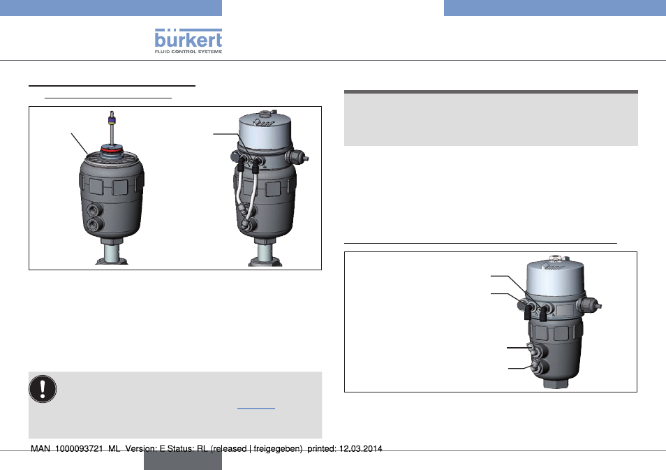
2. installation of the cover ring and
the pneumatic control unit:
Cover ring
Fastening screws
max. 0.5 Nm
Fig. 11: Installation of the cover ring and the Pneumatic Control
Unit, series 20xx
→
Pull the cover ring onto the actuator cover
(for actuator sizes ∅ 50 and ∅ 63 only).
→
Push the Pneumatic Control Unit onto the actuator.
→
Press the Pneumatic Control Unit all the way down as far as the
actuator and turn it into the required position.
Ensure that the pneumatic connections of the Pneumatic
Control Unit and those of the actuator are situated pref-
erably vertically one above the other (see “Fig. 11”).
If they are positioned differently, longer hoses may be
required other than those supplied in the accessory kit.
noTe!
too high torque when screwing in the fastening screw does
not ensure degree of protection ip65 / ip67.
▶ The fastening screws may be tightened to a maximum torque of
0.5 Nm only.
→
Attach the Pneumatic Control Unit to the actuator using the two
side fastening screws. In doing so, tighten the fastening screws
hand-tight only (max. torque: 0.5 Nm).
3. installation of the pneumatic connection on the actuator
Pilot air outlet 2
1
Lower pilot air port
Upper pilot air port
Pilot air outlet 2
2
Fig. 12: Installation of the pneumatic connection, 20xx series
english
Type 8690