7 installation, On process valves of series 21xx, 7installation – Burkert Type 8690 User Manual
Page 12
12
Installation
7
insTallaTiOn
Only for Pneumatic Control Unit without pre-assembled
process valve.
7.1
safety instructions
Danger!
risk of injury from high pressure in the equipment/device.
▶ Before working on equipment or device, switch off the pressure
and deaerate/drain lines.
risk of electric shock.
▶ Before working on equipment or device, switch off the power
supply and secure to prevent reactivation.
▶ Observe applicable accident prevention and safety regulations
for electrical equipment.
Warning!
risk of injury from improper installation.
▶ Installation may be carried out by authorized technicians only
and with the appropriate tools.
risk of injury from unintentional activation of the system and
an uncontrolled restart.
▶ Secure system from unintentional activation.
▶ Following installation, ensure a controlled restart.
7.2
installation of the pneumatic
control unit Type 8690 on
process valves of series 21xx
procedure:
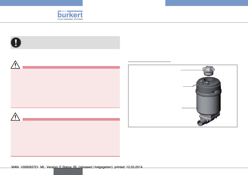
1. install switch spindle:
Transparent cap
Actuator
Pilot air ports
(plug-in hose con-
nectors with collets or
threaded bushings)
Fig. 5: Installation of the switch spindle (1), 21xx series
→
Unscrew the transparent cap on the actuator and unscrew the
position display (yellow cap) on the spindle extension.
→
For model with plug-in hose connector, remove the collets (white
nozzles) from both control air connections (if present).
english
Type 8690