Burkert Type 8690 User Manual
Page 13
13
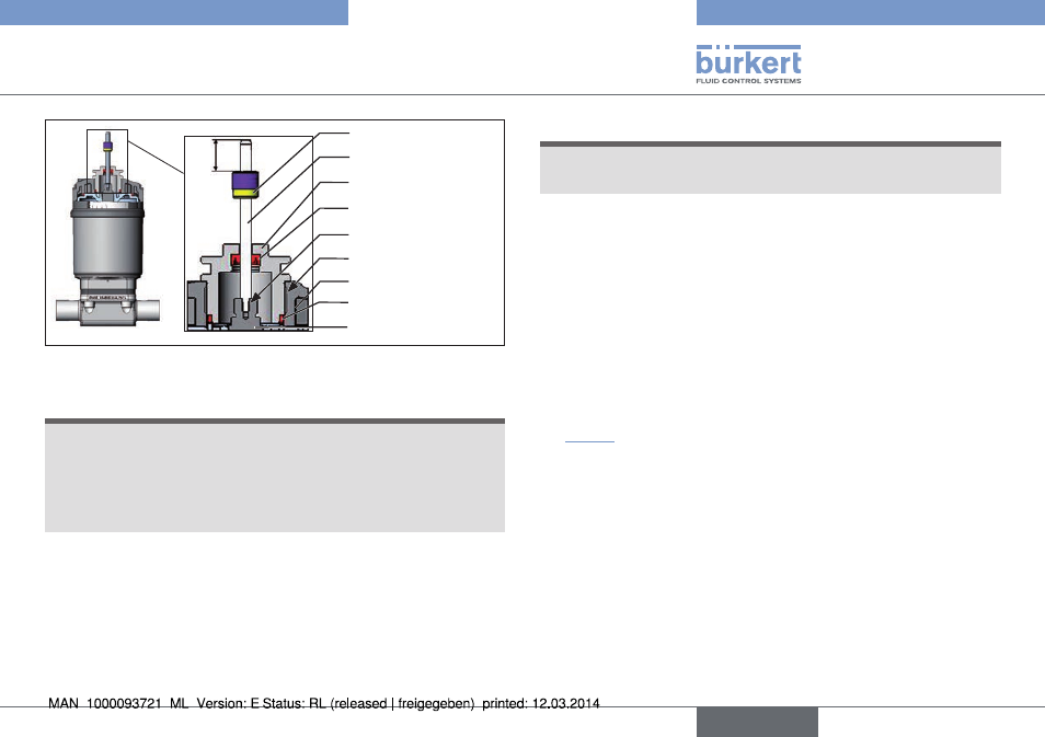
Installation
O-ring
Spindle extension
Guide element
Actuator cover
Groove ring
Switch cam
Switch spindle
10
max. 5 Nm
max. 1 Nm
Fig. 6: Installation of switch spindle (2), 21xx series
noTe!
improper installation may damage the groove ring in the
guide element.
The groove ring is already be pre-assembled in the guide element
and must be “locked into position” in the undercut.
▶ When installing the switch spindle, do not damage the groove ring.
→
Push the switch spindle through the guide element.
noTe!
screw locking paint may contaminate the groove ring.
▶ Do not apply any screw locking paint to the switch spindle.
→
To secure the switch spindle, apply some screw locking paint
(Loctite 290) in the tapped bore of the spindle extension in the
actuator.
→
Check that the O-ring is correctly positioned.
→
Screw the central screw to the actuator cover (maximum torque:
5 Nm).
→
Screw switch spindle onto the spindle extension. To do this,
there is a slot on the upper side (maximum torque: 1 Nm).
→
Position the switch cam on the switch spindle so that the distance
between the switch cam and top of the spindle is 10 mm (see
“Fig. 6”)
english
Type 8690